


Chapter 2 Installation Series 24-HP Instruction Manual
2-12 IM-24-HP
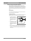
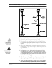
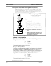
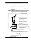
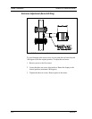
Installing Flow Meters with a Packing Gland Connection*
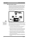
Use the formula below to determine the insertion depth for flow meters
(NPT and flanged) equipped with an insertion tool. To install, see the
next page for instructions for meters with a permanent insertion tool. For
meters with a removable insertion tool, see page 2-14.
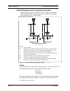
Insertion Length Formula
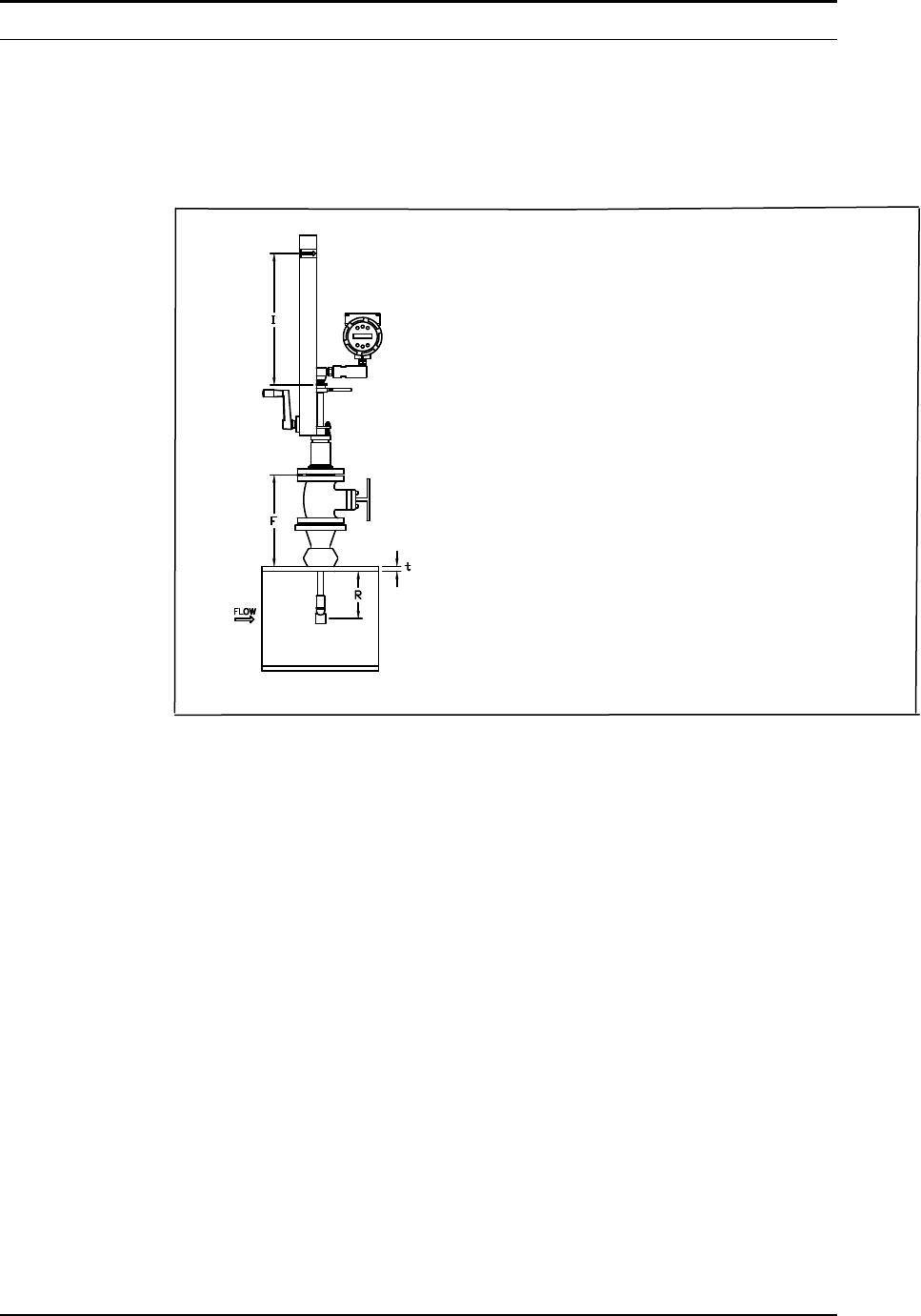
I = F + R + t – 1.35
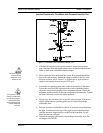
Where:
I = Insertion length.
F = Distance from the raised face of the flange or
top of the process connection for NPT style
meters to the top outside of the process pipe.
R = Pipe inside diameter ÷ 2 for pipes ten inches &
smaller.
R = Five inches for pipe diameters larger than ten
inches.
t = Thickness of the pipe wall. (Measure the disk
cut-out from the tapping procedure or check a
piping handbook for thickness.)
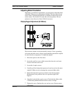
Figure 2-8. Insertion Calculation (Meters with Insertion Tool)
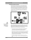
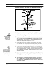
Example 1: Flange Style Meters:
To install a Series 241 Flow Meter into a 14 inch schedule 40 pipe, the fol-
lowing measurements are taken:
F = 12 inches
R = 5 inches
t = 0.438 inches
The example insertion length is 16.09 inches.
Example 2: NPT Style Meters:
The length of thread engagement on the NPT style meters is also subtracted in
the equation. The length of the threaded portion of the NPT meter is 1.18
inches. Measure the thread portion still showing after the installation and sub-
tract that amount from 1.18 inches. This gives you the thread engagement
length. If this cannot be measured use .55 inch for this amount.
F = 12 inches
R = 5 inches
t = 0.438 inches
The example insertion length is 15.54 inches.
*All dimensions are in inches.