Series 24-HP Instruction Manual Chapter 4 Troubleshooting & Repair
IM-24-HP 4-1
Chapter 4 Troubleshooting and Repair
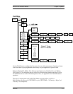
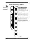
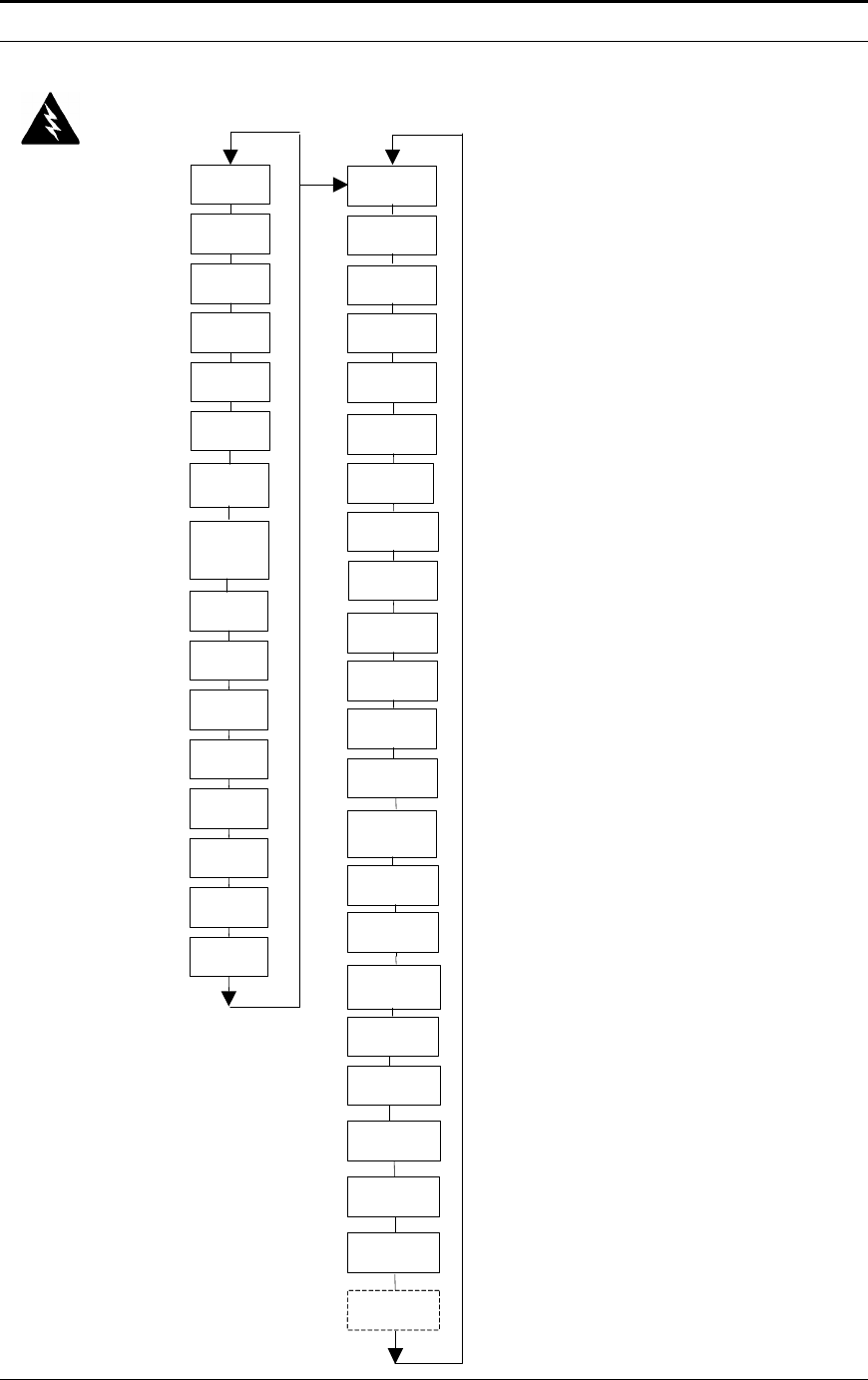
Hidden Diagnostics Menus
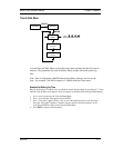
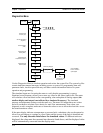
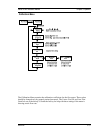
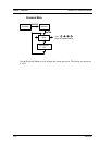
The menus shown to the left can be
accessed using the password 16363, then
moving to the display that reads
“Diagnostics Menu” and pressing ENTER
(rather than one of the arrow keys).
Use the right arrow key to move to the
second column. Press EXIT to move from
the second column back to the first, press
EXIT while in the first column to return to
the setup menus.
Caution: password 16363 will allow full
access to the configuration and should be
used carefully to avoid changes that can
adversely alter the function of the meter.
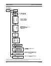
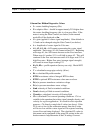
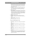
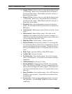
Each of the menus to the left will first be
defined followed by specific troubleshoot-
ing steps.
Warning!
Before attempting any flow
meter repair, verify that the
line is not pressurized.
Always remove main power
before disassembling any
part of the mass flow meter.
Visc = xxxx
Cp
Std = 1.000
Nrml = 1.000
f fi
G A
A1 A2
A3 A4
Kc It
Kb
V
Re
Ck
Lvl
4-20(1),Zero
xxxx
4- 20(1),FScale
xxxx
Alarm (3) Test
Low
Config Code
1BFE
4-20(2),
Fscale
xxxx
4-20(3), Zero
xxxx
*
Not Present on
M22 Models
*
4-20(2), Zero
xxxx
Adj. Filter
xx dB
O
I
Pulse Out Queue
xxxxxxxxxx
TOF
G f
Sig. Rev
Micro Rev
AD R T
F PT V
Spi Err
Rcv Sent
Filter Control
Filter Control
Pres Cal
Current
4-20(3),
Fscale
xxxx
Alarm (1) Test
Low
Alarm (2) Test
Low
Test Pulse Out
Factory Defaults
Reynolds Corr.
Gain Control
Filter Control
Press 9 C’s
More >
RTD 1
More >
RTD 2
More >
Rtd1 = x.x
Rtd2 = x.x
Pe(v) = 0.0
Pv(v) = 0.0
High Pass Filt.
0.33
Meter Type
A2D Ref.
Resistor
2700
Min Delta H
1
**
Energy EMS Meters
Only
**


