


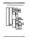


Appendix E MODBUS Commands Series 24-HP Instruction Manual
E-8 IM-24-HP
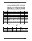
A typical response from the device is as follows: *note these are the older register
definitions
01 04 18 00 00 03 E8 00 00 7A 02 6C 62 00 00 41 BA 87 F2 3E BF FC 6F 42
12 EC 8B 4D D1
01 Device address
04 Function code
18 Number of data bytes = 24
00 00 03 E8 Serial number = 1000 (unsigned long)
00 00 7A 02 Totalizer = 31234 lbm (unsigned long)
6C 62 00 00 Totalizer units = “lb” (string, unused characters are 0)
41 BA 87 F2 Mass flow rate = 23.3164 lbm/sec (float)
3E BF FC 6F Volume flow rate = 0.3750 ft
3
/sec (float)
42 12 EC 8B Pressure = 36.731 psia (float)
4D D1 CRC
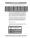
An attempt to read register(s) that don’t exist
01 04 00 00 00 50 F1 D2
01 Device address
04 Function code 4 = read input register
00 00 Starting address
00 50 Number of registers = 80
F0 36 CRC
results in an error response as follows:
01 84 02 C2 C1
01 Device address
84 Function code with most significant bit set indicates error
response
02 Exception code 2 = invalid data address
C2 C1 CRC
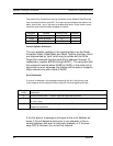
Request the state all three alarms:
01 02 00 00 00 03 38 0B
01 Device address
02 Function code 2 = read discrete inputs
00 00 Starting address
00 03 Number of inputs = 3
38 0B CRC
and the unit responds with:
01 02 01 02 20 49
01 Device address
02 Function code
01 Number of data bytes = 1
02 Alarm #2 on, alarms #1 and #3 off
20 49 CRC
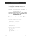
To reset the totalizer:
01 05 00 00 FF 00 8C 3A