DAILY INSPECTION INSTRUCTIONS
3.6
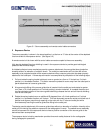
2 Inspect the labels on the exposure device or the transport case to ensure they are legible and
securely attached to the unit. The warning label containing the trefoil should be legible from a
distance of at least 3 ft (approximately 1 m). This label warns the individuals in the immediate vicinity
of the presence of radioactive materials and permits them to take measures to minimize their
exposure to radiation. The printed verbiage and the radiation symbol must be legible. The trefoil
symbol becomes the warning for those individuals who cannot read or understand the written
warning, ‘Caution or Danger, Radioactive Material’. Inspect the legibility and attachment of the source
identification tag that describes the radioactive source contained within the exposure device.
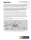
3 Inspect the exposure device’s locking mechanism to ensure the protective covers are installed over
the source assembly connector. Inspect the plunger lock to ensure the lock will engage when the
plunger is depressed and the key is removed. Grasp the entire locking mechanism with one hand and
try to move the lock to determine that the screws have not loosened due to vibration. Unlock the
plunger lock and remove the protective cover. Push the protective cover into the plunger lock
housing for storage during use of the device.
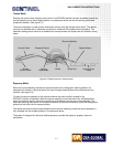
4 Inspect the outlet port for damage and for smooth operation by operating the outlet port cover. Verify
that the outlet port cover rotates smoothly and that the mechanism is not clogged with dirt, grease or
sludge.
Daily Inspection of the Source Guide Tube(s)
1 Remove the protective covers from the swaged fittings on the source guide tubes. Inspect both
swage fittings to ensure the threads are not stripped or clogged with dirt, grease or sludge. Inspect
the ears on the bayonet fitting to ensure they are not bent, broken or excessively worn.
2 Inspect each length of source guide tube(s) that will be used for cuts, inward dents and heat damage.
The inspection is primarily a visual one, but it should include the radiographer using his hands to feel
for the inward dents. This is necessary due to the fact the outer material of the source guide tube is a
flexible waterproof material that can mask dents.
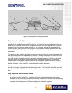
During a visual-only inspection, a dent in the source
guide tube may retain a circular appearance on the exterior, while having an inward dent in the
metallic conduit directly below the waterproof material. This type of masked dent can be felt by the
radiographer's hands. Dents in the source guide tubes are the major cause of source hang-ups.
3 Inspect the source stop (exposure head) to ensure there are no dents, perforations or excessive
wear.
4 Inspect the attachment of the collimator to the source stop (exposure head) if used during
radiography. If collimator utilizes a set screw to affix the collimator to the source stop, hand tighten
only. The use of tools may damage the source stop.
Daily Inspection of the Remote Controls
The remote control consists of a control crank, a control cable with a connector swaged at one end, two
control cable conduits and a connector plug assembly.
The control crank contains a diagonally cut, geared drive wheel that matches the outer helical winding of
the control cable. This worm-gear arrangement of the control crank drive wheel and the control cable
provides the radiographer with a reliable means to project and retract the source assembly from and to
the exposure device. The control crank is equipped with a lever brake that retains the source assembly
while in the exposure head. Beneath the control crank is a label that indicates the direction for EXPOSE
and RETRACT during use in addition to ON and OFF positions for the brake. Control cranks are available
with an odometer to provide the radiographer with the approximate travel distance of the source
assembly. The travel distance is indicated in increments of feet and tenths of a foot. Radiographers can
count the number of rotations of the crank handle when using control cranks that are not equipped with


