


AN.No.G1216B1N000-3D0E
- 14 -
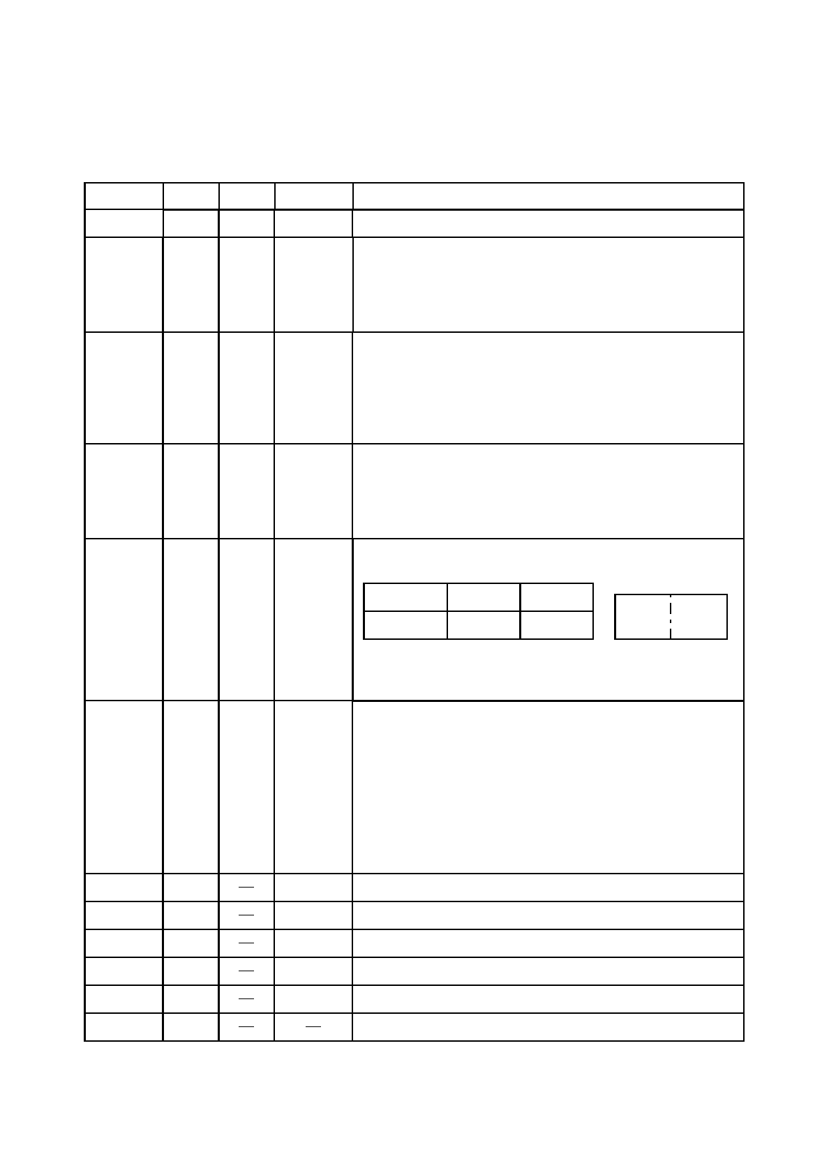
3. OPERATING INSTRUCTIONS
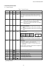
3.1 Terminal Functions
8 I/O MPU
Common terminal for tristate input and output, and data bus.
Functions
Destination
I/O
QTY
Signal
DB
0
to
DB
7
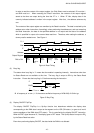
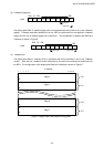
E 1
Enable
Write (R/W=0):Latches data of DB
0
to DB
7
at the fall of E.
Read (R/W=1):Outputs data to DB
0
to DB
7
while “E” keeps a
high level.
Input MPU
R/W 1 Input MPU
Read/Write selection
R/W=1: When E=1 and CS1=0 or CS2=0, the data is output
to DB
0
to DB
7
and read is available by MPU.
R/W=0: When CS1=0 or CS2=0, DB
0
to DB
7
are ready for
receiving the input.
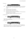
D/I 1 Input MPU
Data/Instruction selection
D/I=1: Indicates that the data in DB
0
to DB
7
is the display
data.
D/I=0: Indicates that the data in DB
0
to DB
7
is the instruction
code.
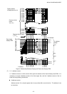
CS1, CS2 2 Input MPU
Chi
p se
l
ect
i
nput.
D
ata
i
nput an
d
output
i
s poss
ibl
e un
d
er
the following status:
Terminal No.
Status
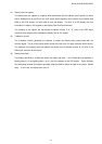
RST 1 Input MPU
Reset signal
Setting the RST signal to a low level allows for initial setup.
(1) ON /OFF register: 0 setup (display OFF)
(2) Display start line register: 0 line setup (display starts
from 0 line)
The setup status is retained until the status is changed by an
instruction after reset is released.
V
DD
1 Power Power terminal for logic (+5 V)
V
SS
1 Power GND terminal (0 V)
V
LC
1 Power Power terminal for LC drive
LEDA 1 Power LED backlight anode terminal
1
F
GND
terminal is connected to the metallic frame of the module. Use this terminal when
grounding the frame.
LEDC 1 Power LED backlight cathode terminal
F
GND
1 Frame ground
1
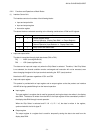
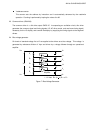
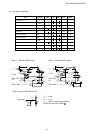
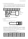
CS2CS1
LCM display screen
CS1
0
CS2
0
CS1
:
C
ontro
l
s t
h
e
LCM
l
e
f
t
h
a
lf
di
sp
l
ay screen
(SEG1
to
SEG64).
CS2: Controls the LCM right half display screen (SEG65 to
SEG128).
Table 1 Terminal Functions