AN.No.G1216B1N000-3D0E
- 17 -
3.4 Instructions
3.4.1 General
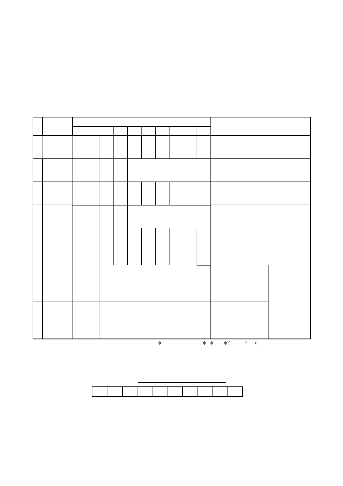
Instructions are listed on Table 2. Instructions other than the Status Read instruction will not be
executed if they are sent while another instruction is already being executed. The busy flag is “1”
when executing the instruction. Check whether or not the flag is “1” before transmitting the
instructions from the MPU.
1
R/W D / I DB
7
DB
6
DB
5
DB
4
DB
3
DB
2
DB
1
DB
0
Code
Instruction
Function
Display
ON / OFF
Display start
line
X-address
(page) set
Y-address
set
Status read
Display data
write
Display data
read
0 0 0 0 1 1 1 1 1 1/0
0 0 1 1
Display start lines
( 0 to 63 )
0 0 0 1
Y-address
( 0 to 63 )
1 0
B
U
S
Y
0
ON
/
OFF
R
E
S
E
T
0 0 0
0 0 1 0 1 1 1
X-address(page)
(0 to 7)
0 1 Write Data
1 1 Read Data
Turns ON / OFF total display. Data and
internal status in the display RAM remain
unchanged.
1: ON 0 : OFF
Determines the RAM line to be displayed on the
top line (COM1) on the display.
Sets the X-address of the RAM (page) in the
X-address (page) register.
Set Y-address of the RAM in the Y-address
counter.
Reads the status.
RESET 1: Reset 0: Normal
ON/OFF 1: Display OFF 0: Display ON
BUSY 1: during internal operation
0: READY status
Accesses the
RAM in which
address has been
specified
beforehand. After
that the Y-address
advances by one.
2
3
4
5
6
7
Note: The BUSY time varies depending upon the frequency F (:215 kHz (typ.) ) of 1, 2 (1/F T
BUSY
3/F ).
0
Writes data DB
0
(LSB) to
DB
7
(MSB ) on the data
bus into the display RAM.
Reads data DB
0
(LSB) to
DB
7
(MSB) from the
display RAM into the data
bus.
3.4.2 Detailed explanation
(1) Display ON/OFF
DB
0
Code
D/I DB
7
0 0 1 1 1 1 1 D
R/W
0 0
Turns the display ON when D=1, and OFF when D=0. When the display is turned OFF by D=0, the
original display appears if D is set to 1 because the display data is retained in the display data RAM.
Table 2 List of Instructions


