SILICONSYSTEMS PROPRIETARY
This document and the information contained within it is confidential and proprietary to SiliconSystems, Inc.
All unauthorized use and/or reproduction is prohibited.
PAGE 6JUNE 17, 2008 DOCUMENT: 3650H-02DSR
SSD-HXXX(I)-3650 DATA SHEET ELECTRICAL SPECIFICATION
SIGNAL DESCRIPTIONS
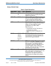
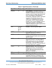
Table 8: Signal Descriptions
Signal Name Pin(s) Type Description
A2-A0 36, 33,
35
I Address Inputs. These signals are
asserted by the host to access the task
registers in the device.
-CS0,-CS1 37, 38 I In the true IDE mode, -CS0 is the chip
select for the task file registers while -CS1
is used to select the Alternate Status
register and the Device Control register.
-CSEL 28 I Cable Select. This internally pulled-up
signal is used to configure this device as a
master or a slave when the jumper
configuration is in CSEL mode.
When this pin is:
• Grounded by the host, this device is
configured as a master.
• Open, this device is configured as a
slave.
D15-D0 18, 16,
14, 12,
10, 8, 6,
4, 3, 5, 7,
9, 11, 13,
15, 17
I/O Data Inputs/Outputs. This is the 8-bit or
16-bit bidirectional interface between the
host and device. The lower eight bits are
used for 8-bit register transfers.
-DMACK 29 I DMA Acknowledge. This signal is used by
the host in response to DMARQ to initiate
DMA transfers. The DMARQ/-DMACK
handshake is used to provide flow control
during the transfer. When -DMACK is
asserted, -CS0 and -CS1 are not asserted
and transfers are 16-bits wide.
DASP 39 I/O Disk Active/Slave Present. This open
drain output signal is asserted low any time
the drive is active. In a master/slave
configuration, this signal is used by the
slave to inform the master that a slave is
present.


