


Si53xx-RM
Rev. 0.5 75
6.9.5.1. PLL Lock Detect (Si5316, Si5323, Si5366)
The PLL lock detection algorithm indicates the lock status on the LOL output pin. The algorithm works by
continuously monitoring the phase of the input clock in relation to the phase of the feedback clock. If the time
between two consecutive phase cycle slips is greater than the Retrigger Time, the PLL is in lock. The LOL output
has a guaranteed minimum pulse width as shown in (Table 8, “AC Characteristics—All Devices”). The LOL pin is
also held in the active state during an internal PLL calibration.
The retrigger time is automatically set based on the PLL closed loop bandwidth (See Table 34).
6.9.5.2. Lock Detect (Si5322, Si5365)
A PLL loss of lock indicator is not available for these devices.
6.10. Device Reset
Upon powerup, the device internally executes a power-on-reset (POR) which resets the internal device logic. The
pin RST
can also be used to initiate a reset. The device stays in this state until a valid CKINn is present, when it
then performs a PLL Self-Calibration (See “6.2. PLL Self-Calibration”).
6.11. DSPLLsim Configuration Software
To simplify frequency planning, loop bandwidth selection, and general device configuration of the Any-Frequency
Precision Clocks. Silicon Laboratories offers the DSPLLsim configuration utility for this purpose. This software is
available to download from www.silabs.com/timing.
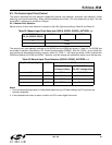
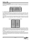
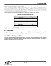
Table 34. Lock Detect Retrigger Time
PLL Bandwidth Setting (BW) Retrigger Time (ms)
60–120 Hz 53
120–240 Hz 26.5
240–480 Hz 13.3
480–960 Hz 6.6
960–1920 Hz 3.3
1920–3840 Hz 1.66
3840–7680 Hz .833