


Si53xx-RM
Rev. 0.5 67
6.3. Pin Control Input Clock Control
This section describes the clock selection capabilities (manual input selection, automatic input selection, hitless
switching, and revertive switching). When switching between two clocks, LOL may temporarily go high if the two
clocks differ in frequency by more than 100 ppm.
6.3.1. Manual Clock Selection
Manual control of input clock selection is chosen via the CS[1:0] pins according to Table 22 and Table 23.
The manual input clock selection settings for the Si5365 and the Si5366 are shown in Table 23. The Si5366 has
two modes of operation (See Section “6.5. Frame Synchronization (Si5366)”). With CK_CONF = 0, any of the four
input clocks may be selected manually; however, when CK_CONF = 1 the inputs are paired, CKIN1 is paired with
CKIN3 and likewise for CKIN2 and CKIN4. Therefore, only two settings are available to select one of the two pairs.
Notes:
1. To avoid clock switching based on intermediate states during a CS state change, the CS input pins are
internally deglitched.
2. If the selected clock enters an alarm condition, the PLL enters digital hold mode.
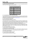
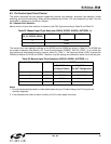
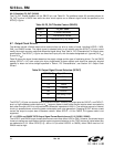
Table 22. Manual Input Clock Selection (Si5316, Si5322, Si5323), AUTOSEL = L
CS (Si5316)
CS_CA (Si5322, Si5323)
Si5316 Si5322 Si5323
0CKIN1
1CKIN2
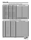
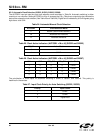
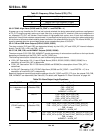
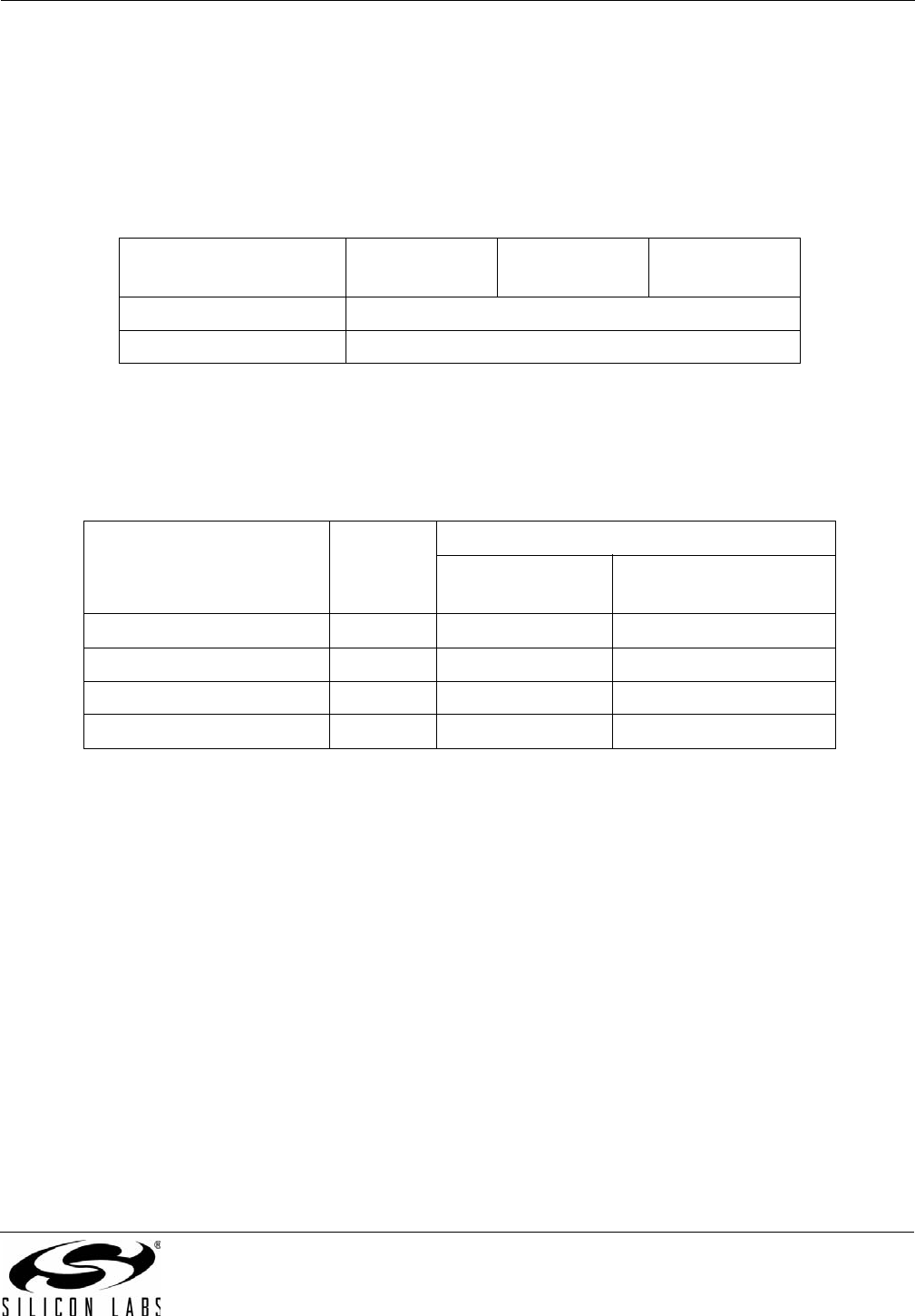
Table 23. Manual Input Clock Selection (Si5365, Si5366), AUTOSEL = L
[CS1_CA4, CS0_CA3]_Pins Si5365 Si5366
CK_CONF = 0
(5 Output Clocks)
CK_CONF = 1
(FS_OUT Configuration)
00 CKIN1 CKIN1 CKIN1/CKIN3
01 CKIN2 CKIN2 CKIN2/CKIN4
10 CKIN3 CKIN3 Reserved
11 CKIN4 CKIN4 Reserved