


10
SWITCHING ON AND OFF
2 OPERATION
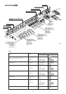
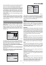
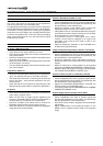
will operate but it may be unable to read certain input signals
correctly.
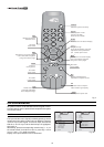
Switching on the system:
• from the remote control (keys 0-9)
• from the Display keypad (keys and ).
Typically, the picture will appear after 15-20 seconds. Pressing
a key from 1-9 on the remote control selects the corresponding
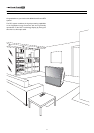
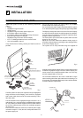
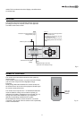
The RTX system consists of the Display and the DigiOptical
Image Processor (which is also the system control centre). The
DigiOptical Image Processor sends commands to the Display
and receives operating status information from the Display and
function commands from the user. The system can be controlled
from either the remote control (via the infrared sensors on the
DigiOptical Image Processor and on the Display) or the keypad
located on the top of the Display.
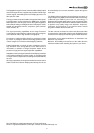
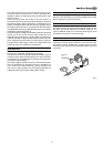
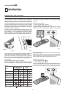
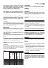
The two units have separate power supplies however: after
connecting the unit to the electrical mains supply, set the two
power switches to “I”; the DigiOptical Image Processor power
switch is located on the external power supply unit (Fig. 6a),
while the Display switch is on the Display rear panel (Fig. 6b).
Off
Initialisation
Status
DigiOptical Image
Processor
Display
Green LED Blue LED Front LED
Keyboard pad
Stand-by
On
Cooling
Optical link not active
Caution
Error
: Off
: On
: Flashing
: Insignificant
--
--
-
-
-
--
E
SC
MEN
U
AU
T
O
0
E
SC
MEN
U
AU
T
O
Table 3
input; pressing 0 selects the input active at the time the system
was last switched off.
If the system is switched on very soon after it was last switched
off, the lamp may fail to come on because it is too hot. In this
case just wait a few minutes to allow the lamp to cool.
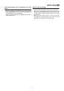
Switching the system off :
• from the remote control (
key)
• from the Display keypad (
key).
If you wish to power off the system completely, wait at least one
minute in stand-by before setting the mains power switches on
the units to the “O” position or disconnecting the power supply
Fig. 7
Fig. 8
O
I
Fig. 6bFig. 6a
After a few seconds (system initialisation interval), the DigiOptical
Image Processor and the Display assume stand-by mode.
System status information is provided by two LEDs (green and
blue) on the front panel of the DigiOptical Image Processor, a
blue LED on the front of the Display, and the keypad status (off
or illuminated).
Significant status signals are given in Table 3.
If the “No optical link” or “Error” signals are active the system
cannot be operated; if the “Warning” signal is active the system