


6
CONNECTING THE TWO UNITS
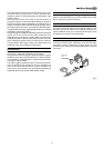
The RTX system consists of two separate units (the DigiOptical
Image Processor and the Display), each of which is equipped
with a power cable; the two units are interconnected by a 20 m
fibre optic cable.
The ideal location for the DigiOptical Image Processor is on a
cabinet shelf or on a rack (dimensions compatible with a standard
19" rack). Make sure that the support surface is stable and that
the unit has sufficient space around it for ventilation purposes
(at least 3 cm).
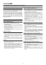
The unit is connected to the mains via an external power supply
unit with an output of +7 Vdc; the unit’s main power switch is on
the power supply unit.
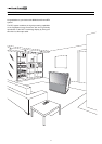
Display
Alimentatore
DigiOptical
Image Processor
Remote Control
1.5 V AAA-
type batteries
Power cables
Europe, UK, US (x2)
DigiOptical
Image Processor
Three-core
fibre optic cable
Instruction
Manual
D
I
G
I
O
P
T
I
C
A
L
I
M
A
G
E
P
R
O
C
E
S
S
O
R
O
I
DigiOptical Image
Processor power supply unit
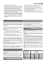
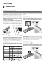
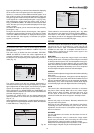
1 INSTALLATION
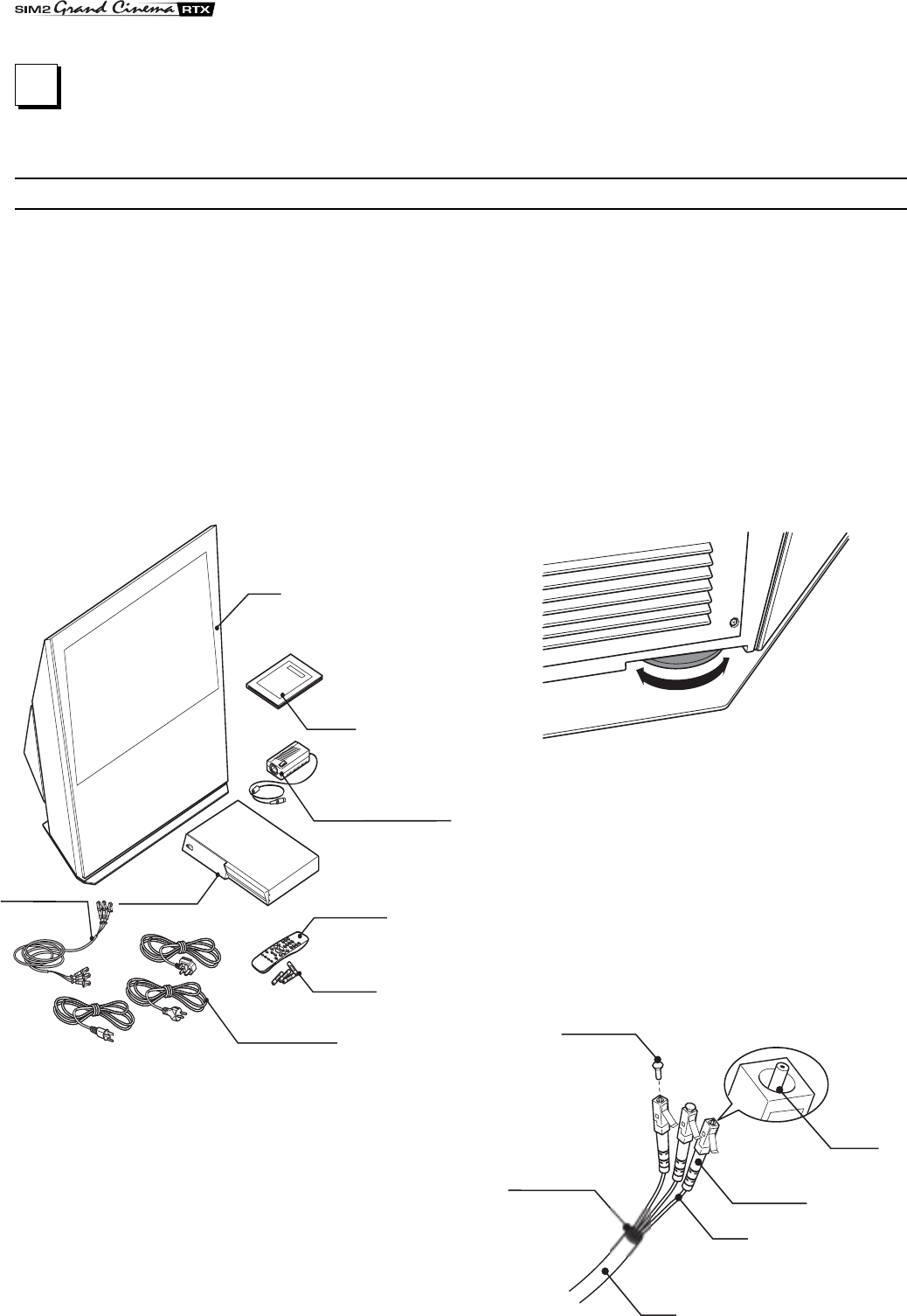
SIM2’s RTX system is made up of the following components
(Fig.1):
• Display
• DigiOptical Image Processor
• remote control
• DigiOptical Image Processor power supply unit
• three power cables for the Display
• three power cables for the DigiOptical Image Processor
• triple fibre optic cable for linking the
DigiOptical Image Processor and the Display
• four 1.5 V AAA-type batteries for the remote control
• User and installation manual
If any accessories are missing, contact your Dealer as soon as
possible.
Connect the power supply unit output cable to the POWER
socket located on the rear panel (Fig. 4).
Use exclusively the power supply unit provided with the system
or an alternative power supply unit expressly approved by SIM2.
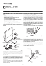
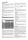
The Display is designed to stand on the floor. Place the Display
on a flat, level surface where it has sufficient space for ventilation;
to prevent glare and reflections, avoid places exposed to direct
sunlight or intense light sources.
The mains power input socket and the power switch are both
located on the rear panel.
Adjust the rear feet to obtain the optimum viewing angle in
accordance with the distance and height of the viewing position
in front of the Display (Fig. 2).
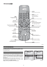
The system can be fully controlled using the supplied IR
Fig. 1
(infrared) remote control handset. There is a single remote control
for both the DigiOptical Image Processor and the Display; the
remote control can be directed towards either unit since they
are both equipped with an IR sensor.
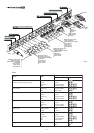
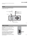
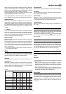
The connection between the two units is made with a single
cable containing three fibre optic cables each terminating in an
LC connector. The standard cable length of 20 m will be sufficient
for most installation requirements.
Fig. 2
Cavo
Fibra
Ferrule
Connettore
Tappo di
protezione
Punto di
sfiocco
Protective cap
Separation point
Cable
Connector
Fibre
Fig. 3