


9
The video signals that can be connected to this input can have
horizontal scanning frequencies of 15 kHz (standard video
resolution), 32 kHz, or higher (progressive scanning video, high
definition video).
Some sources provide the facility to choose between a
progressive signal or an interlaced signal. Although in general a
progressive signal is higher quality than an interlaced signal, it
is often preferable to perform the deinterlacing operation on the
RTX system rather than on the source because the RTX system
is equipped with Faroudja’s sophisticated directional correlation
deinterlacing technology (DCDi™).
Progressive signals usually provide better quality than interlaced
signals, but if the source features both progressive and
deinterlaced signal outputs it is good practice to compare the
quality of the pictures reproduced by the RTX system in the two
cases: deinterlacing performed by the RTX system (thanks to
Faroudja DCDi™ technology) is often more effective than that
performed at the source (typically a DVD player).
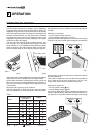
RGB GRAPHICS
This input should be connected to an RGB-type video or graphic
signal using a cable with a DB15HD type connector.
The signal source device (typically a personal computer or game
console) must be able to provide separate H/V synchronisation
or composite H+V synchronisation or composite synchronisation
on the green signal (RGsB).
The video or graphic signals that can be connected to this input
can have horizontal scan frequencies (H-sync) of between 15
and 110 kHz and a vertical frequency (V-sync) of between 40
and 100 Hz. Image resolution can vary between 640x480 and
1600x1200 pixels (VGA, SVGA, XGA, SXGA, UXGA).
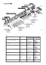
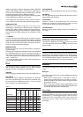
3
1
2
3
3
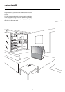
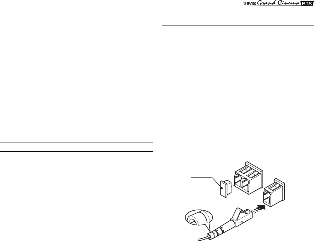
Protective
cap
Fig. 5
DVI-D
If your source is equipped with this type of output (increasingly
present on the latest PCs) you can take advantage of the better
picture quality by using the DVI-D input.
CONTROL (RS232)
The system can be controlled via a personal computer or home
automation systems by means of the serial port: simply connect
this input via a serial cable from an RS232 serial port. On
request, SIM2 will send you a document containing the serial
port settings and the list of main commands.
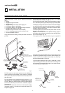
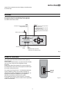
FIBRE OPTIC LINK
After removing the protective caps from the fibre optic cable
connectors and the panel connectors, insert the fibre optic
connectors carefully, matching the numbers shown on each
element. Be very careful when handling optical fibres cable and
connectors.