


16
8. Press evenly the module onto the PC/104 stack.
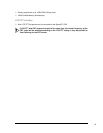
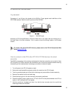
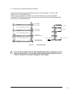
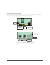
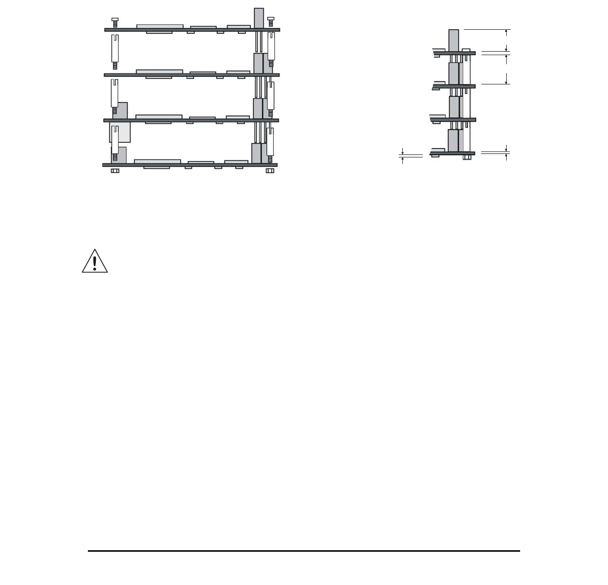
The picture below shows a typical module stack with 2 PC/104 modules, 1 PC/104 16-BIT
module, and 1 PC/104 8-BIT module.
The maximum configuration for the PCI bus of PC/104 modules is 4 plus the Host Board.
If standard PC/104 modules are used in the stack, they must be the top module(s) because they
will normally not include the PCI bus.
0.6 in. (15mm) Spacers (4 plcs.)
Stackthrough
8-bit module
0.435 in. (11 mm)
0.6 in. (15 mm)
Stackthrough
16-bit module
Stackthrough
PC/104Plus module
Non-Stackthrough
PC/104Plus module
0.6 in. (15mm) Spacers (4 plcs.)
0.6 in. (15mm) Spacers (4 plcs.)
0.100 in. (2.54 mm)
0.062 in. (1.57 mm)
Figure 5. The Module Stack
Do not force the module onto the stack! Wiggling the module or applying too much
pressure may damage it. If the module does not readily press into place, remove it,
check for bent pins or out-of-place keying pins, and try again.