


25
25
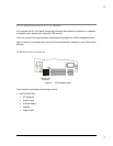
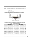
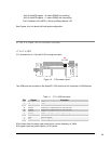
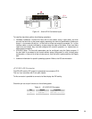
Serial 2
Serial 1
J6
J5
Figure 12. J5 and J6 Connectors layout
Both can be set as RS232 but only one (J5) can be set as RS422-485.
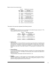
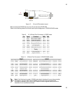
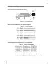
Refer to the following tables for the serial ports pinout assignment in RS232/422/485 modes.
Table 9. J5, J6 Serial Port Connectors in RS232 mode
Pin Signal Function DB25 DB9
1 DCD Data Carrier Detect 8 1
2 DSR Data Set Ready 6 6
3 RX Receive Data 3 2
4 RTS Request To Send 4 7
5 TX Transmit data 2 3
6 CTS Clear To Send 5 8
7 DTR Data Terminal
Ready
20 4
8 RI Ring Indicator 22 9
9,10 GND Signal Ground 7 5
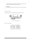
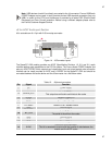
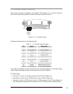
Table 10. J5 Serial Port Connector in RS422-RS485 modes
RS422 RS485
Pin Signal Function In/out Signal Function In/out Pin
1
-TX Transmit data out -TX/-RX Transmit/Receive data out/in
1
2
-- Not connected -- -- Not connected --
2
3
+TX Transmit Data out +TX/+RX Transmit/Receive data out/in
3
4
-- Not connected -- -- Not connected --
4
5
-RX Receive Data in -- Not connected --
5
6
-- Not connected -- -- Not connected --
6
7
+RX Receive Data in -- Not connected --
7
8
-- Not connected -- -- Not connected --
8
9,10
gnd Signal ground -- gnd Signal ground --
9,10
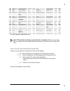
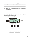
Note. If the Serial port is used in RS485 mode, the bi-directional line must be controlled
via software, using the Data Terminal Ready (DTR) signal of the serial controller.
This signal is defined by bit 0 of the UART Modem Control Register (MCR) and the bi-
directional line is controlled as follows: