


18
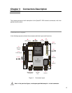
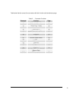
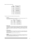
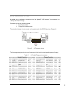
Below is shown the connector pinout:
Table 3. Multifunction connector
Pin Signal Function
1
SPKR- Speaker output
2
SPKR+ Speaker output (+5V)
3
RESET External reset
4
WDTL Watch dog timeout latch
5
KBD Keyboard data
6
KBC Keyboard clock
7
GND Ground signal
8
KBP Keyboard power (+5V)
9
BAT External Battery input
10
P_B External Power Button
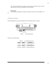
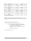
This section of the connector implements the following functions:
Keyboard
An AT compatible keyboard can be connected to the module through connector J3. The
following table lists the pin-out of connector J3.
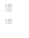
Table 4. Keyboard connector
Pin Signal Function
5
KBD Keyboard data
6
KBC Keyboard clock
7
GND Ground signal
8
+5V Power supply
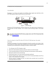
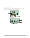
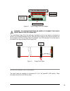
System reset
Connecting the pin 3 of the multifunction connector to ground performs a hardware reset
of the module. It is possible to use an external push-button, normally open. J3 provides a
connection for an external normally-open pushbutton to manually reset the system.
Connect the other side of the switch to ground. The reset signal is “de-bounced” on the
board.
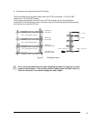
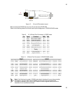
External Battery
Pin 9 of the multifunction connector allows the connection of an external backup battery
(typically from 3 to 3.9 V). This battery is used at power down to preserve the date-time in
the Real Time Clock.
The typical battery consumption with the module off is 7 uA.
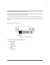
Speaker
A transistor to supply 0.1 watt of power to an external speaker controls these outputs. A
transistor amplifier buffers the speaker signal. Use a small general purpose 2 or 3-inch
permanent magnet speaker with an 8-ohm voice coil.