


23
23
14
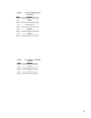
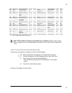
GND Signal ground -- 20 GND Signal ground
14
15
PD6 Printer Data 6 out 8 MTR0# (*) Motor On 0 In/out
15
16
GND Signal ground -- 21 GND Signal ground --
16
17
PD7 MSB Printer
Data
out 9 MEDIA-ID1# (*) In
17
18
GND Signal ground -- 22 GND Signal ground --
18
19
ACK# (*) Character
accepted
in 10 DS1# Drive Select 1 Out
19
20
GND Signal ground -- 23 GND Signal ground --
20
21
BSY Busy in 11 MTR1# (*) Motor On 1 Out
21
22
GND Signal ground -- 24 GND Signal ground --
22
23
PE Paper End in 12 WDATA# (*) Write Disk
Data
Out
23
24
GND Signal ground -- 25 GND Signal ground --
24
25
SLCT Ready To
Receive
in 13 WGATE# (*) Write Gate Out
25
26
NC Reserved -- --- --- --- ---
26
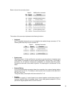
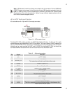
(*) The “#” stands for: signal active low
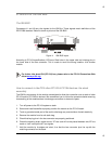
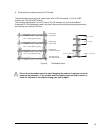
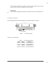
Note. FDD shouldn’t be directly connected to the J4 connector. Before using a Floppy
Disk, an adapter must be inserted between the parallel port flat cable and the Floppy Disk
Drive.
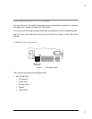
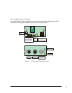
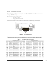
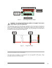
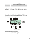
HOW TO USE THE PARVUS FDD ADAPTER
There are two configurations available for the Parvus FDD Adapter:
1. - J1A :Male configuration (for plugging to the Floppy Disk Flat Cable)
2.- J1 :Female configuration (for direct plugging to the Floppy Disk Drive)
J2 :Power supply (5V) used to power the adapter.
(This connector can’t power the FDD that needs its normal power
supply).
J3 :Parallel Port Flat Cable Connector
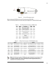
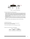
A picture of this adapter is shown below.