


SMA Technologie AG Electrical Connection
Installation Guide SMC50A_60A-IEN073320 Page 37
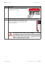
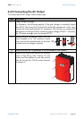
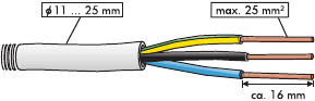
3. Cable Connection
The connection terminals in the Sunny Mini
Central are suitable for wire cross-sections
of up to 25 mm².
The external diameter of the cable must
therefore be between 11 mm and 25 mm.
If you use a cable with a cross-section
smaller than 14 mm (11 mm minimum), the
rubber bushing in the screw fitting must be replaced by the one included with the
inverter at delivery.
Strip approximately 16 mm of the insulation from the conductors of the cable. The
connection is made with three wires (L, N, PE).
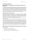
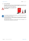
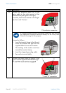
4. Additional Grounding of the Housing
As well as the main protective earth connection at the AC terminal, the Sunny Mini
Central is also equipped with an additional protective earth connection directly on
the housing. This can be used if a second protective earth connection is required
by the energy supply company.
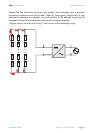
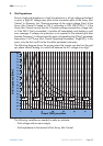
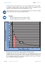
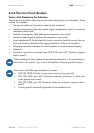
5. Wire Design
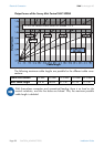
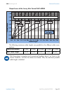
Do not use cables where the losses will exceed 1.0 %!
For optimum operation of the inverter, the grid impedance of the AC cable must
not exceed 1 Ohm. This is necessary, amongst other things, for the correct
operation of the impedance monitoring. The cable cross-section should be
dimensioned so output losses do not exceed 1 % at the nominal power. Output
losses depending on the cable length and cross-section are shown in the graphs
below. Multi-wire cables with copper forward and return conductors are used.
Use the following diagrams to check your wire design:
Externa
l
diameter
Wi
re cross-
section