


AR-B1570 User’s Guide
19
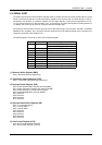
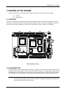
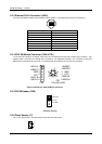
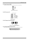
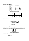
3.2.7 Power Connector (PWR2)
The PWR2 is a 4-pin power connector. It’s the standard connectors on all Acrosser boards.
3 GND
2 GND
1 +12
4 +5
PWR2
PWR2: 4-Pin Power Connector
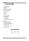
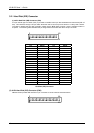
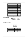
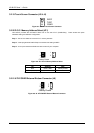
3.2.8 CRT Connector (P4)
P4 (CRT Connector)
6
10
15
11
1
2
3
4
5
1 Red
2 Green
3 Blue
13 Horizontial
14 Vertical Sync
4, 9, & 11 Not used
5 & 10 Ground
6, 7 & 8 AGND
12 DDC DATA
15 DDC CLOCK
P4: CRT Connector
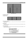
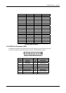
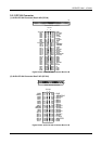
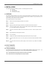
3.2.9 LCD Supported Voltage Select (JP4)
Factory Preset
5V3.3V
1
2
3
4
5
6
1
2
3
4
5
6
Figure 0-3 JP4: LCD Supported Voltage Select
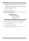
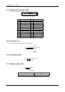
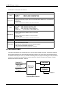
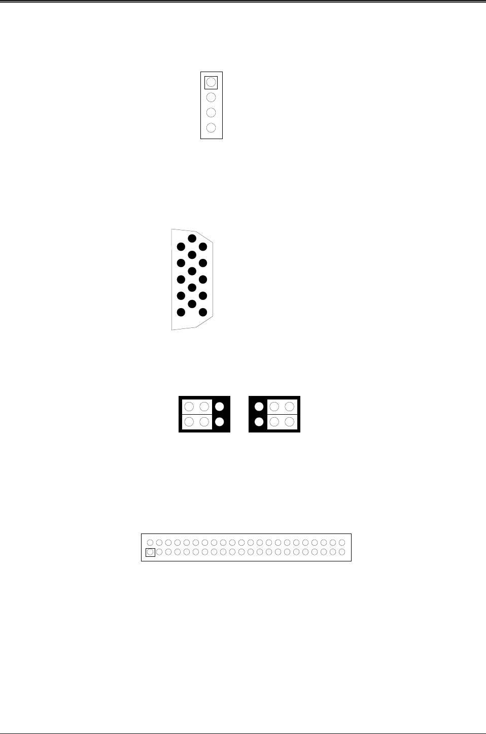
3.2.10 LCD Panel Display Connector (LCD1)
Attach a display panel connector to this 44-pin connector with pin assignments as shown below:
1
2
Figure 0-4 LCD1: LCD Display Connector