


AR-B1570 User’s Guide
24
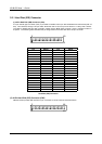
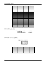
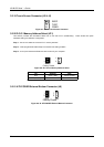
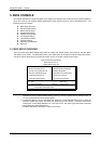
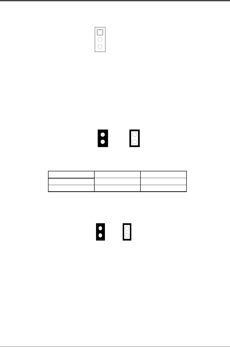
3.2.19 Touch Screen Connector (J3 & J4)
1 RXDF
2 TXDF
3 CGND
Figure 0-7 J3&J4: Touch Screen Connector
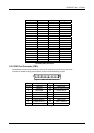
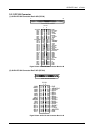
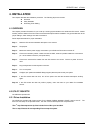
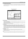
3.2.20 D.O.C. Memory Address Select (JP1)
This section provides the information about how to use the D.O.C. (DiskOnChip). There divided two parts:
hardware setting and software configuration.
Step 1:
Use JP1 to select the correct D.O.C. memory address.
Step 2:
Insert programmed DiskOnChip into sockets U19 setting as DOC.
Step 3:
Line up and insert the AR-B1570 card into slot of your computer.
OFF
Factory Preset
1
2
1
2
ON
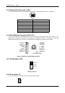
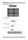
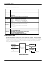
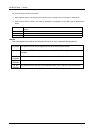
Figure 0-8 JP1: D.O.C. Memory Address Select
JP1 Address Note
OFF CE00 : 0000 Factory Preset
ON D200 : 0000
Table 0-4 D.O.C. Memory Address
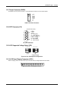
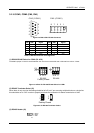
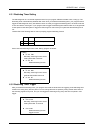
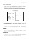
3.2.21 ATX POWER External Bottom Connector (J6)
OFF
Factory Preset
1
2
1
2
ON
Figure 0-9 J6: ATX POWER External Bottom Connector