


AR-B1570 User’s Guide
23
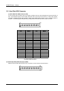
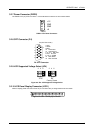
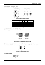
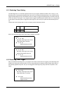
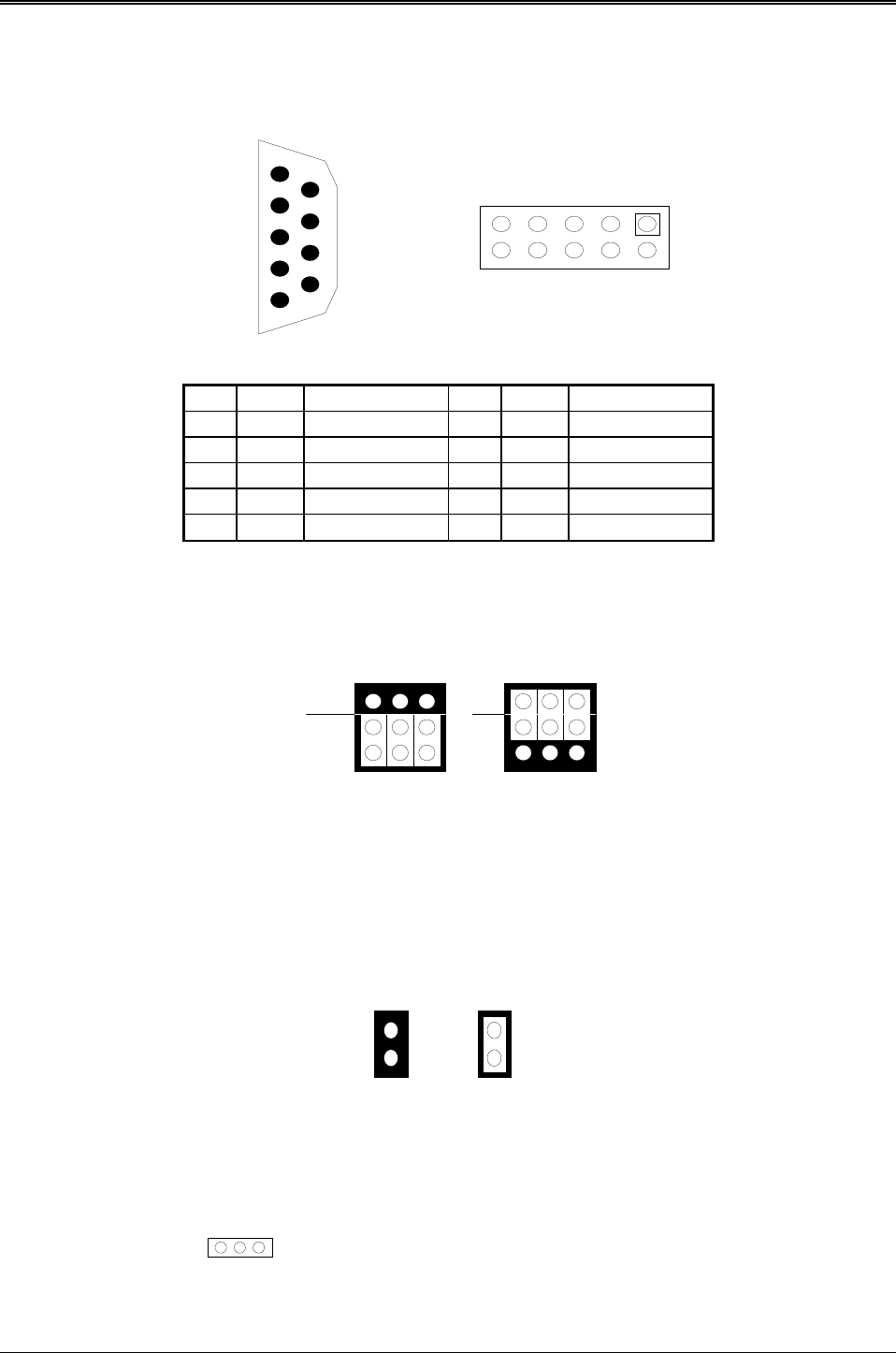
3.2.18 COM1, COM2 (CN5, CN6)
CN5 (COM1) CN6 (COM2)
9
8
7
6
5
4
3
2
1
1
2
3
4
5
6
7
8
9
10
Figure 0-5 CN5 & CN6: RS-232 Connector
CN5 CN6 Signal CN5 DB6 Signal
1 1 /DCD 8 6 /CTS
6 2 /DSR 4 7 /DTR
2 3 RXD 9 8 /RI
7 4 /RTS 5 9 VCC
3 5 TXD -- 10 VCC
Table 0-3 RS-232 Connector Pin Assignment
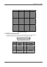
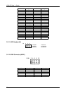
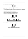
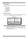
(1) RS-232/RS-485 Select for COM1 (P2 & P3)
The P2&P3 jumper is used to choose between the use of the on-board RS-232 or RS-485 for the CN5 – COM1.
P2
P3
1
3
2
RS-232
Factory Preset
1
3
2
RS-485
A
C
B
A
C
B
Figure 3-10 P2 & P3: RS-232/RS-485 Select for COM1
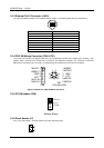
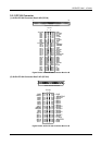
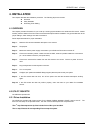
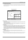
(2) RS-485 Terminator Select (J2)
When there is only one line the setting should be left off, but if you are using multiple blocks on a single line
this should be set to “ON” in order to properly terminate the connection for better transmission of data
OFF
Factory Preset
1
2
1
2
ON
Figure 0-6 J2: RS-485 Terminator Select
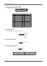
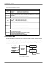
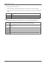
(3) RS-485 Header (J9)
1 2 3
1 N485+
2 N485-
3 GND
J9