


12
Chapter 1 Overview
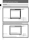
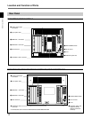
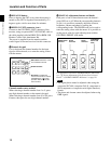
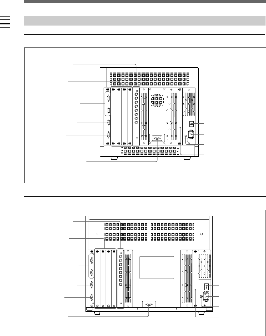
Rear Panel
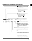
BVM-D24E1WU/D24E1WE/D24E1WA/D32E1WU/D32E1WE/D32E1WA
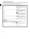
BVM-D20F1U/D20F1E/D20F1A
Location and Function of Parts
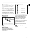
1 MAIN POWER switch
2 AC IN socket
3 Fuse
4 Deflection option slot
9 ISR connector
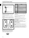
5 Analog input/output
connectors
7 REMOTE 1 connectors
8 REMOTE 2 connector
!º CONTROL UNIT connector
1 MAIN POWER switch
2 AC IN socket
3 Fuse
4 Deflection option slot
(Digital uniformity
adaptor installed as
standard)
9 ISR connector
5 Analog input/output
connectors
6 Input option slots
7 REMOTE 1 connectors
8 REMOTE 2 connector
!º CONTROL UNIT
connector
6 Input option slots
• The illustration above shows the BVM-D24E1WU/D24E1WE/D24E1WA.