


52
Chapter 2 Menu
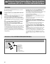
[C7] Adjusting Beam Landing and Digital Uniformity (SET UP 7)
— WHITE UNIFORMITY Menu
Setting Lists of the WHITE UNIFORMITY Menu
This section explains the setting lists displayed in the
menu.
How to read the setting lists
• For purposes of explanation, each setting list is
preceded by a menu number. These numbers are not
displayed on the screen.
For more information about the menu number, see “About
menu numbers” on page 23.
• The arrow mark (÷) refers you to another setting list
that appears after you make the setting, or to an
operation that is carried out as a result of the setting.
When there is no arrow mark, the menu does not have
any sub-list.
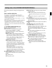
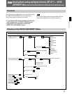
[C7] WHITE UNIFORMITY menu (1/2)
Adjust the shift of beam landing which occurs due to
the earth’s magnetism (LANDING ADJUST menu).
Select the method of adjustment in this menu.
MANUAL... : Adjust with the MANUAL knobs.
÷[C71]
AUTO... : Automatically adjust using the Sony BKM-
14L Auto Setup Probe. ÷[C72]
SIGNAL: Select the white signal to be used for
adjustment.
EXT: Use an external input signal. When
adjusting the gain, input the appropriate signal.
INT: Use an internal white signal.
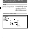
[C7] WHITE UNIFORMITY menu (2/2)
Adjust the color unevenness of the CRT (DIGITAL
UNIFORMITY ADJ menu). Select the method of
adjustment in this menu.
MANUAL... : Adjust with the MANUAL knobs.
÷[C73]
AUTO FULL POINTS... : Automatically adjust the
whole area of the screen in sequence using the
Sony BKM-14L Auto Setup Probe. ÷[C74]
AUTO ONE POINT... : Automatically adjust the
selected adjustment point of the screen only using
the Sony BKM-14L Auto Setup Probe. ÷[C75]
ORIGINAL VALUE: Set the initial value.
Select the signal format from 1035/60I, 1080/60I,
1080/50I, 1080/48I, 480/60P, 480/60I, 575/50P,
570/50I and 720/60P, and the screen size from
16:9-NORM, 16:9-UNDR, 4:3-NORM and 4:3-
UNDR.
Note
4:3-NORM and 4:3-UNDR can be combined with
480/60P, 480/60I, 575/50P and 570/50I only.
SIGNAL: Select the white signal to be used for
adjustment.
EXT: Use an external input signal. When adjusting
the gain, input the appropriate signal.
INT: Use an internal white signal.
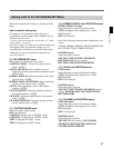
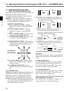
[C71] MANUAL menu
Select the rough or fine adjustment of beam landing.
First perform the rough adjustment, then proceed to the
fine adjustment.
DIRECTION : Adjust the beam landing shift
approximately by selecting the direction in which
the monitor is facing.÷[C711]
FINE ADJUST : Adjust the beam landing shift finely
at each adjustment point on the screen. ÷[C712]
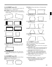
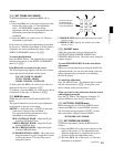
[C711] DIRECTION menu
Display the white signal and select the direction using
the UP/DOWN buttons or PHASE knob where the
white is most uniform on the screen.
NORTH, NORTH EAST, EAST, SOUTH EAST,
SOUTH, SOUTH WEST, WEST or NORTH WEST
[C712] FINE ADJUST menu
Display the white signal, select the adjustment point on
the screen, and adjust the white at the selected point as
uniformly as possible using the UP/DOWN buttons or
PHASE knob.
NS: Correct the beam landing shift at the top center and
bottom center of the screen simultaneously.
TOP LEFT: Correct the beam landing shift at the top
left of the screen.
TOP RIGHT: Correct the beam landing shift at the top
right of the screen.
BOTTOM LEFT: Correct the beam landing shift at
the bottom left of the screen.
BOTTOM RIGHT: Correct the beam landing shift at
the bottom right of the screen.
RESET: Reset the beam landing data at all the five
points above to the center simultaneously.
When you want to erase characters from the screen
while adjusting manually
Press the [F1] button. The characters disappear. To
display characters, press the [F1] button again.
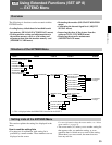
[C72] AUTO menu
Before entering the AUTO menu, connect the BKM-
14L to the OPTION connector.
The following message appears.÷[C721]
SET PROBE ON CURSOR