


14
Chapter 1 Overview
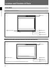
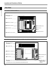
Location and Function of Parts
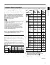
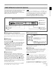
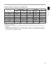
8 REMOTE 2 connector (female, D-sub 9-pin)
Forms a parallel switch and controls the monitor
externally. The pin assignment and factory setting
function assigned to each pin are given below.
Cable with D-sub 9-pin plugs (not supplied)
Monitor 1
Monitor 2
Pin number
1
Set input signal channel 1 (numeric keypad
function)
2 Set input signal channel 2 (numeric keypad
function)
3 Select sync signal (SYNC button function)
4 Set the screen to monochrome, or set for
automatic switching based on the input signal
(MONO MODE button function)
5 Safe area on/off (SAFE AREA button
function)
6, 7 Not connected
8 Tally lamp on/off
9 Ground
Function
15
96
REMOTE 1
IN
OUT
REMOTE 1
IN
OUT
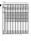
All pin function assignments can be changed with the
REMOTE menu.
For information about the REMOTE menu, see “ [C2]
Assigning the Remote Control Functions (SET UP 2) —
REMOTE Menu” on page 40.
To switch each function between on and off or
between enable and disable, change pin connections in
the following way.
ON or enabled: Short each pin and pin 9 together.
OFF or disabled: Leave each pin open.
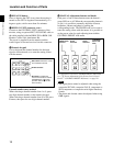
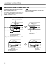
9 ISR (Interactive Status Reporting) connector
(female, D-sub 9-pin)
Connect to the ISR system.
!º CONTROL UNIT connector (female, D-sub 9-
pin)
Connects the BKM-10R Monitor Control Unit using a
cable with D-sub 9-pin plugs such as an RCC-5G/10G/
30G (not supplied) or the cable supplied with the
BKM-32H/34H Monitor Control Unit Attachment Kit.
REMOTE 1 IN connector
REMOTE 1 OUT connector
REMOTE 1
IN
OUT
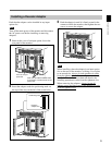
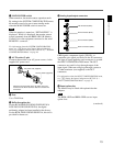
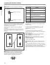
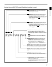
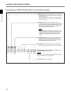
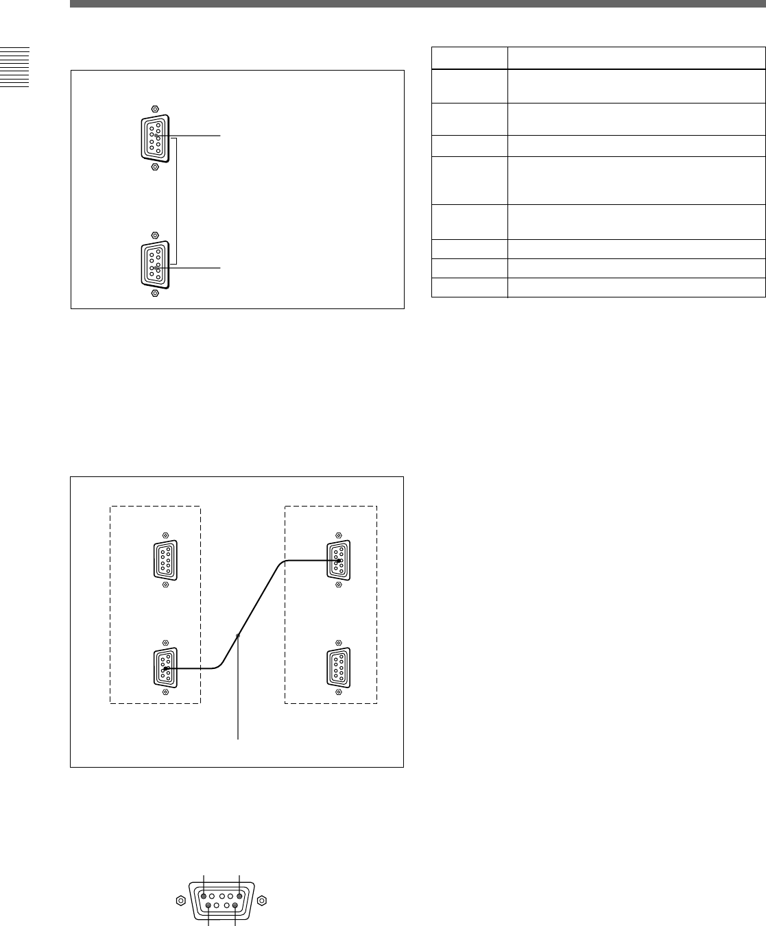
7 REMOTE 1 connectors (female, D-sub 9-pin)
These are RS-485 serial interface connectors, used for
connecting two or more BVM-Dxx, BVM-xxE/F/G
and HDM-xxE series monitors.
The IN and OUT connectors form a loop-through
connection.
Connect two monitors using a cable with D-sub 9-pin
plugs such as an RCC-5G (not supplied) as shown in
the figure.