


29
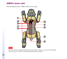
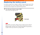
Knowing more about AIBO
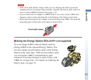
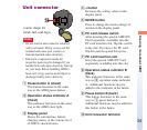
Unit connector
Notes
• Do not touch a unit connector terminal
with your hands. Doing so may soil the
terminal and cause poor contact, or
transmit harmful static electricity.
• Electronic components inside the
respective parts may be damaged if you
handle them with static electricity built up
on your body. Before handling AIBO’s
head, tail, or leg, touch a metal object to
discharge bodily static electricity.
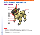
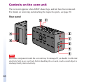
1 Pause button A (chest)
This button functions in the same
way as the AIBO pause button.
2 Operation status indicator A
(chest)
This indicator functions in the same
way as the AIBO chest light.
3 Display panel
Shows the current time, battery
charging status, or the volume level
of AIBO’s musical tones.
4 + button
Increases the setting values in the
display panel.
5 MODE button
Press to change the mode settings of
an item in the display panel.
6 PC card release switch
After inserting the special AIBO PC
Card (separately available) into the
PC card insertion slot, flip this switch
to the side. To remove the PC card,
flip this switch up and then press.
7 PC card insertion slot
Insert the special AIBO PC Card
(separately available) into this slot.
8 Operation status indicator B
(back)
This indicator functions in the same
way as 2 operation status indicator
A. Additional functions may be
added to this indicator in the future.
9 Pause button B (back)
This button functions in the same
way as 1 pause button A.
Additional functions may be added to
this button in the future.
q; Unit connector terminal
(same shape for
head, tail, and legs)