


– 3 –
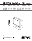
KP-41S5/41S5B/41S5G/
41S5K/41S5R/41S5U
RM-862
TABLE OF CONTENTS
(CAUTION)
SHORT CIRCUIT THE ANODE OF THE PICTURE TUBE AND
THE ANODE CAP TO THE METAL CHASSIS, CRT SHIELD, OR
CARBON PAINTED ON THE CRT, AFTER REMOVING THE AN-
ODE.
SAFETY-RELATED COMPONENT WARNING!!
COMPONENTS IDENTIFIED BY SHADING AND MARK ! ON
THE SCHEMATIC DIAGRAMS, EXPLODED VIEWS AND IN THE
PARTS LIST ARE CRITICAL TO SAFE OPERATION. REPLACE
THESECOMPONENTS WITH SONY PARTS WHOSE PART NUM-
BERS APPEAR AS SHOWN IN THIS MANUAL OR IN SUPPLE-
MENTS PUBLISHED BY SONY. CIRCUIT ADJUSTMENTS THAT
ARE CRITICAL TO SAFEOPERATION ARE IDENTIFIED IN THIS
MANUAL. FOLLOW THESE PROCEDURES WHENEVER CRITI-
CAL COMPONENTS ARE REPLACED OR IMPROPER OPERA-
TION IS SUSPECTED.
Section Title Page
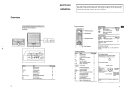
1. GENERAL
Overview ..............................................................................................................4
Getting Started
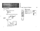
Step 1 Preparation ................................................................................................5
Step 2 Tuning in to TV Stations ...........................................................................5
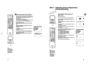
Step 3 Adjusting Colour Registration (Convergence) ..........................................6
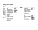
Additional Presetting Functions ...........................................................................7
Operating Instructions
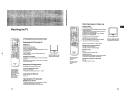
Watching the TV ..................................................................................................9
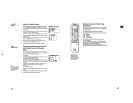
Adjusting and Setting the TV Using the Menu ..................................................10
Teletext ..............................................................................................................11
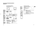
Connecting and Operating Optional Equipment ................................................12
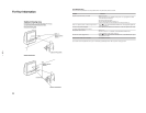
For Your Information.......................................................................................... 14
Optimum Viewing Area....................................................................................14
Troubleshooting................................................................................................14
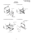
2. DISASSEMBLY
2-1. Rear Board Removal .................................................................................15
2-2. Main Bracket Section Removal.................................................................15
2-3. Service Position.........................................................................................15
2-4. G Board Removal ......................................................................................15
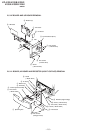
2-5. AE Board and UE Board Removal............................................................16
2-6. H1 Board, H2 Board and Resistor (High Voltage)Removal ......................16
2-7. BEZNET Section Removal .......................................................................17
2-8. High-Voltage Cable Installation and Removal ..........................................17
2-9. Mechasel Assy Removal ............................................................................17
2-10.Chassis Block Removal .............................................................................18
3. SET-UP ADJUSTMENTS
3-1. Screen Voltage Adjustment ........................................................................19
3-2. Focus Lens Adjustment .............................................................................19
3-3. SCREEN (G2) Adjustment........................................................................19
3-4. Focus VR Adjustment................................................................................ 19
3-5. Deflection Yoke Tilt Adjustment ...............................................................20
3-6. 2-Pole Magnet Adjustment........................................................................20
3-7. 4-Pole Magnet Adjustment........................................................................20
3-8. Defocus Adjustment (Blue) .......................................................................20
4. SAFETY RELATED ADJUSTMENT
4-1. HV Hold Down Adjustment ......................................................................21
5. CIRCUIT ADJUSTMENTS
5-1. Electrical Adjustments...............................................................................22
How to enter into service mode.................................................................22
5-2. Service list .................................................................................................24
5-3. Registration (Convergence) Adjustment Method .................................... 27
PAL Registration Adjustment....................................................................27
Center Adjustment ..................................................................................... 27
Size Adjustment ......................................................................................... 27
5-4. Geometry ................................................................................................... 27
Main Deflection Adjustment .....................................................................27
Sub Deflection Adjustment Item ...............................................................28
Vertical Line Adjustment...........................................................................28
Horizontal Line Adjustment ......................................................................29
Size and Linearity Adjustment ..................................................................29
Horizontal Size Adjustment ......................................................................29
Green Vertical Linearity Adjustment ......................................................... 29
Green Vertical Size Adjustment .................................................................30
Green Horizontal Trapezoidal Distortion Adjustment ..............................30
Green Horizontal Quaternary Adjustment.................................................30
Green Horizontal Asymmetrical Pin Distortion Adjustment.....................30
Green Horizontal Symmetrical Pin Distortion Adjustment.......................31
Green Vertical Wave (3rd-Order) Distortion Adjustment..........................31
Green Vertical 4th Order Distortion Adjustment......................................31
Green Vertical Trapezoidal Distortion Adjustment ...................................31
Green Vertical Asymmetrical Pin Distortion (2nd-Order Distortion)
Adjustment ................................................................................................32
Green Vertical Asymmetrical Pin Distortion Adjustment .........................32
Green and Red Registration Adjustment ...................................................32
Green and Blue Adjustment ......................................................................32
Registration Data Write .............................................................................32
5-5. AGC Adjustment ....................................................................................... 32
5-6. White Balance Adjustment........................................................................33
5-7. Text Position Adjustment ..........................................................................33
6. DIAGRAMS
6-1. Block Diagram (1).....................................................................................35
Block Diagram (2).....................................................................................39
6-2. Frame Schematic Diagram ........................................................................43
6-3. Circuit Boards Location ............................................................................46
6-4. Printed Wiring Boards and Schematic Diagrams ......................................46
• G Board ...................................................................................................47
• AE(1/2) Board .........................................................................................55
• AE(2/2) Board .........................................................................................60
• H1 Board .................................................................................................65
• H2 Board .................................................................................................66
• E Board ...................................................................................................67
• D Board ...................................................................................................73
• ZR Board.................................................................................................80
• ZG Board ................................................................................................81
• CR Board ................................................................................................83
• CG Board ................................................................................................84
• CB Board ................................................................................................86
• UE Board ................................................................................................87
6-5. Semiconductors .........................................................................................88
7. EXPLODED VIEWS
7-1. SCREEN AND COVER .............................................................................90
7-2. CABINET AND PANEL BLOCK..............................................................91
7-3. CHASSIS AND PICTURE TUBE..............................................................92
8. ELECTRICAL PARTS LIST.......................................................... 93
Section Title Page