


– 32 –
KP-41S5/41S5B/41S5G/
41S5K/41S5R/41S5U
RM-862
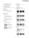
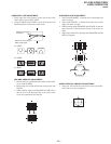
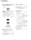
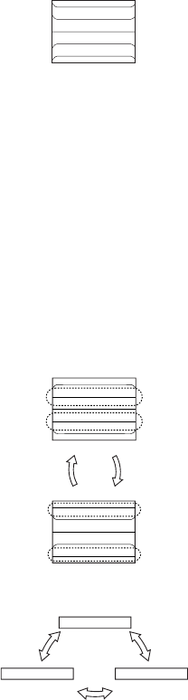
GREEN VERTICAL ASYMMETRICAL PIN DISTORTION
(2ND-ORDER DISTORTION) ADJUSTMENT
1. Correct the asymmetrical pin distortion at the top and bot-
tom of the screen with GV SBOW.
GV SBOW
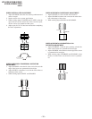
GREEN VERTICAL ASYMMETRICAL PIN DISTORTION
ADJUSTMENT
1. Using GV MPIN adjust the pin distortion at both edges of
the screen and at the centre.
2. Using GV PIN, adjust, so that the horizontal lines at the top
& bottom of the screen are straight lines.
3. Adjust GV MPIN & GV PIN so that there is no curve in the
horizontal lines on the entire screen.
4. After adjusting the items above, using tracking with GV
SBOW. GV MPIN, and GV PIN to correct the entire screen.
MPIN
PIN
GV SBOW
GV MPIN GV PIN
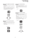
GREEN AND RED REGISTRATION ADJUSTMENT
1. Receive a PAL cross-hatch signal.
2. Adjust so that the red lines lay on the green lines.
Adjust, using the same procedure as the GREEN SUB ad-
justment outline above.
Note : Main registration correction should not be while ad-
justing Red adjustment.
BEWARE : Not to change Green Sub Items It’ s easily done
by mistake.
GREEN AND BLUE ADJUSTMENT
1. Adjust so that the blue and green lines are on top of each
other.
Note : Main registration correction should not be while ad-
justing Blue adjustment.
BEWARE : Not to change Green & Red Sub Items.
It’ s easily done by mistake.
REGISTRATION DATA WRITE
* Points to bear in mind :
There are two independent modes of pictures 4 : 3 MODE
and 16 : 9 MODE
1. Once REGISTRATION 4 : 3 has been adjusted
Press "Mute" + 0 >"Data Write"
(write data in NVM)
Press "On screen disp." + 0 >"WRT 5060" Pal to NTSC
(write data Pal/Secam to NTSC)
If 2 + 0 is pressed (Data copy) it is recording
data from 4 : 3 to 16 : 9 mode.
So it should be adjusted in 16 : 9 mode.
2. Adjust REGISTRATION in 16 : 9 mode.
Press "Mute" + 0 >"Data Write"
(write data in NVM)
Press "On screen disp." + 0 >"WRT 5060"Pal to NTSC
(write Pal/Secam to NTSC)
3. Once REGISTRATION has been adjusted in both modes
(4 : 3 and 16 : 9)
a) With picture go into service mode
b) Press TT and "autoconvergence" button in
control panel and wait for the adjusting
∗ Make sure input signal is PAL. If input signal is NTSC
and do this process, NTSC data are copied to PAL data!
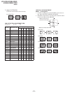
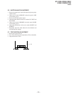
5-5. AGC ADJUSTMENT
1. Receive an off-air signal.
2. Adjust the AGC VR ( IF 1001 ) so that there is no snow noise
and cross-modulation.