


6
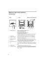
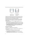
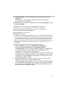
Names of parts and functions
Wireless Unit
1 STATUS indicator Indicates the status of the Wireless Unit.
Booting: quickly flashes white.
Normal : slowly flashes white
During firmware update : flashes red
During Quick Setup : flashes red
If firmware update fails : continues flashing red after firmware
update (from this state, you must update the firmware again).
2 Reset switch Returns the Wireless Unit settings to their factory defaults.
3 LINK/ACT indicator Lights when an Ethernet cable is connected to the NETWORK
connector on the Power Unit.
4 Wireless unit cable Connects to the WIRELESS UNIT connector on the Power Unit.
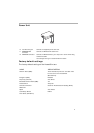
5 Rear cover Remove this cover if you want to hang the Wireless Unit to a wall
and to verify the MAC address and Network Name (SSID).
6 Wall mounting holes Use these holes to hang the Wireless Unit to the wall.
7 ID The six-character hexadecimal unique product ID is printed here.
This ID is used as the default Network Name (SSID) of the Wireless
Unit.
8 MAC address The Wireless Unit MAC address is printed here.
9 Quick Setup switch Use this switch to set up the Wireless LAN Converter PCWA-DE30.
Refer to the Quick Start Guide of the Wireless LAN Converter or
Help for details.
Front Rear (With rear cover removed)
7
89