


13
GB
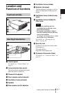
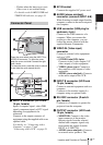
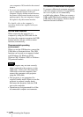
Location and Function of Controls
Overview
– Flashes when the lamp cover or air
filter cover is not secured firmly.
For details on the LAMP/COVER and
TEMP/FAN indicator, see page 43.
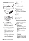
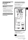
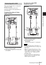
1 INPUT A connector (HD D-sub
15-pin, female)
Inputs a computer signal, video GBR
signal, component signal, or DTV signal
depending on equipment to be
connected.
Connects to the output connector of
equipment using the supplied cable or an
optional cable.
For details, see “Connecting with a
Computer” on page 17 and
“Connecting with a VCR” on page 19.
2 AC IN socket
Connects the supplied AC power cord.
3 AUDIO (stereo minijack)
connector (common INPUT A/B)
When listening to sound output from the
computer, connect to the audio output of
the computer.
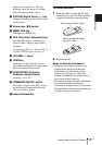
4 USB connector (USB plug for
upstream, 4-pin)
Connect to the USB connector of a
computer. When you connect the
projector to the computer, you can
control the mouse function with the
supplied Remote Commander.
5 VIDEO IN (Video input)
connector
Connect to external video equipment
such as a VCR.
• S VIDEO (mini DIN 4-pin):
Connects to the S video output (Y/C
video output) of video equipment.
• VIDEO (phono type): Connects to
the composite video output of video
equipment.
• AUDIO (stereo minijack): Connects
to the audio output of the VCR.
6 INPUT B connector (HD D-sub
15-pin, female)
Connect to external equipment such as a
computer.
Connects to the monitor output of a
computer using an optional cable.
7 RS-232C connector (D-sub 9-
pin, female)
Connects to a computer to operate the
projector from the computer.
8 OUTPUT connector (HD D-sub
15-pin, female)
• MONITOR: Connect to the video
input connector of the monitor.
Outputs signals from the selected
channel and computer signals only
from among the signals from the
INPUT A or INPUT B.
• AUDIO (stereo minijack): Connects
to external active speakers. The
Connector Panel
VIDEOS VIDEO AUDIO
AUDIO
AUDIOMONITOR
INPUT A
VIDEO IN
OUTPUT
INPUT B
REMOTE RS-232C
PUSH SLIDE
1
2
VIDEO
S VIDEO
AUDIO
AUDIO
AUDIOMONITOR
INPUT A
INPUT A/B
VIDEO IN
OUTPUT
INPUT B
REMOTE
RS-232C
COVER
LOCK/UNLOCK
6
7
8
5
4
3
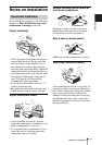
Open the cover when using the INPUT B or
VIDEO IN connector. To open the cover,
push the cover and slide it toward the right
until it locks.
To close the cover, press the cover to unlock
it and slide the cover toward the left.