


Monaco Technical Reference Spectrum Signal Processing
Introduction
4
Part Number 500-00191
Revision 2.00
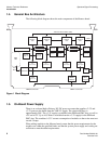
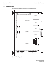
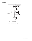
1.4. General Bus Architecture
The following block diagram shows the main components of the Monaco board.
1.5. On-Board Power Supply
There is an on-board high-efficiency DC-DC power converter that supplies +2.5V and
+3.3V power to the board from the VME 5V supply. The circuit efficiency is
approximately 90%. The +3.3V supply is available to the PEM and PMC sites, as well as
+5V and ±12V. Up to 16.5 Watts is available from the +3.3V supply for the PEM and
PMC sites. The combined +3.3V current consumption of modules on these sites must not
exceed 5 Amps.
When adding modules to the Monaco board, ensure that the power requirements for the
modules are within the specified limits, and that the system power supply and cooling are
sufficient to meet the added requirements.
SBSRAM
128K x 32
Address Buffer
and
Data Latches
Hurricane
PMC
Site
Test Bus
Controller
VME P1 Connector
SDRAM
4M x 32
DSP~LINK3 Interface
Node A
'C6x
Node B
'C6x
Node C
'C6x
Node D
'C6x
PEM Site
PCI
Bus
VME P2 Connector
Global Shared
SRAM
512K x 32
Address Buffer
and
Data Latches
Address Buffer
and
Data Latches
Address Buffer
and
Data Latches
SBSRAM
128K x 32
SDRAM
4M x 32
SBSRAM
128K x 32
SDRAM
4M x 32
SBSRAM
128K x 32
SDRAM
4M x 32
PEM Site
Global Shared Bus
SCV64
VME64
Interface
A24 VME
Slave
Interface
JTAG
'C6x Host Port Inteface (HPI)
Figure 1 Block Diagram