


Spectrum Signal Processing Monaco Technical Reference
DSP~LINK3 Interface
Part Number 500-00191
31
Revision 2.00
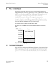
5.3. Interface Signals
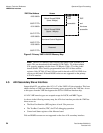
The DSP~LINK3 interface consists of two 16-bit bi-directional buffers for data, a 16-bit
address latch, and a control signal buffer. The control signals are terminated via a SCSI
terminator. The DSP~LINK3 interface signals are:
• 32 data I/O lines: D[31..0]
• 16 address outputs: A[15..0] A15 and A14 are used for slave device (board)
selection.
• /DSTRB, /ASTRB, R/W and /RST outputs
• Tri-state ready (/RDY) input
• 4 open-collector interrupt inputs (IRQ0 to IRQ3). These interrupt are logically
OR’ed and routed to the INT7 line of node A’s ‘C6x.
Refer to DSP~LINK3 specification for details (available from Spectrum’s internet web
site at http://www.spectrumsignal.com)
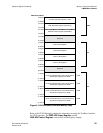
5.4. DSP~LINK3 Reset
Bit D0 of the DSP~LINK3 register controls the DSP~LINK3 reset line. This register is
located at address 016D 8018h of node A. Setting bit D0 to “1” asserts the DSP~LINK3
reset line; setting it to “0” releases the reset. DSP~LINK3 resets must be at least 1 µs
long. This reset is entirely under software control.
The DSP~LINK3 reset line will also be asserted during /SYSRESET or secondary
control register board reset conditions.