


4-Port USB 2.0 Hub Controller
Datasheet
Revision 1.63 (03-30-07) Page 20 SMSC USB20H04
DATASHEET
Chapter 8 Implementation Notes
The following sections consist of select functional explanations to aid in implementing the Hub Controller
into a system.
8.1 Configuration Implementations
The USB20H04 is normally configured by an external EEPROM connected directly to the serial interface.
Typical circuit diagrams are shown below. For a more detailed discussion of the serial interface, including
how to configure the USB20H04 using the SMBus mode, please see Application Note 9.29, "USB20H04 4-
Port USB 2.0 Hub Controller, Configuration Programming". The Application Note also discusses designing
a Hub system that supports In Circuit Programming of the EEPROM.
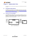
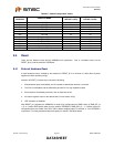
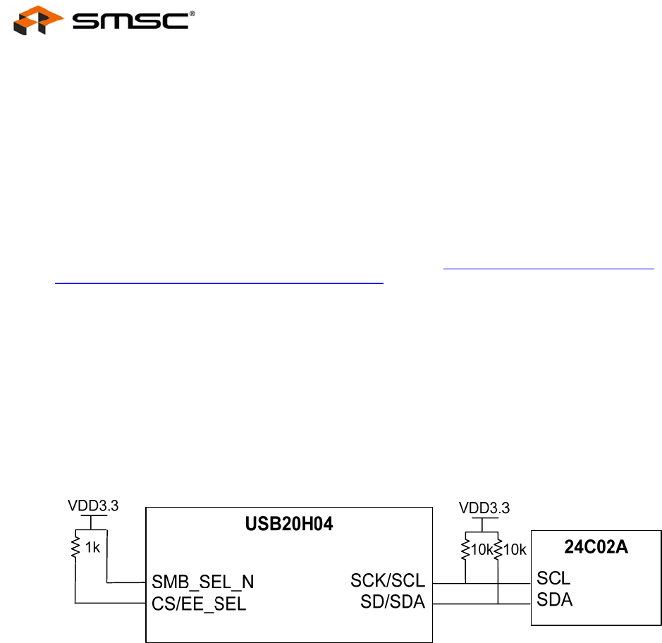
8.1.1 Interfacing a 2-wire Serial EEPROM
The I
2
C EEPROM interface is designed to attach to a single “dedicated” I
2
C EEPROM. It conforms to the
Standard-mode I
2
C Specification (100kbit/s transfer rate and 7-bit addressing) for protocol and electrical
compatibility. The circuit board designer is required to place external pull-up resistors (10K ohm
recommended) on the SDA & SCL lines (per SMBus 1.0 Specification, and EEPROM manufacturer
guidelines) to VDD in order to assure proper operation.
Figure 8.1 - 2-Wire EEPROM Interface