


Integrated USB 2.0 Compatible 7-Port Hub
Datasheet
SMSC USB2507 11 Revision 2.3 (08-27-07)
DATASHEET
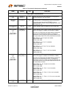
Port 4 Amber
LED
&
LED Enable
strapping option
AM4/
LED_EN
I/O12 Amber indicator LED for port 4. Will be active low when LED
support is enabled via EEPROM or SMBus.
If the hub is configured by the internal default configuration,
this pin will be sampled at RESET_N negation to determine
if LED support is enabled or disabled. Also, the active state
of the LED will be determined as follows:
‘0’ = LED support is disabled, LED is inactive
‘1’ = LED Support is enabled, LED is active low.
Port 3 Amber
LED
AM3 I/O12 Amber indicator LED for port 3. Signal will be active low.
Port 2 Amber
LED
&
MTT Disable
AM2/
MTT_EN
I/O12 Amber indicator LED for port 2. Will be active low when LED
support is enabled via EEPROM or SMBus.
If the hub is configured by the internal default configuration,
this pin will be sampled at RESET_N negation to determine
if MTT support is disabled (STT only). Also, the active state
of the LED will be determined as follows:
‘0’ = MTT support is disabled, LED is active high
‘1’ = MTT support is enabled, LED is active low.
Port 1 Amber
LED
&
Gang Power
Switching and
Current Sensing
strapping option.
AM1/
GANG_EN
I/O12 Amber indicator LED for port 1, Will be active low when LED
support is enabled via EEPROM or SMBus.
If the hub is configured by the internal default configuration,
this pin will be sampled at RESET_N negation to determine
if downstream port power switching and current sensing are
ganged, or individual port-by-port. Also, the active state of
the LED will be determined as follows:
‘0’ = Port-by-port sensing & switching, LED is active high
‘1’ = Ganged sensing & switching, LED is active low.
Port Power
Polarity strapping.
PRTPWR_POL I/O12 Port Power Polarity strapping determination for the active
signal polarity of the 7:1PRTPWR pins.
While RESET_N is asserted, the logic state of this pin will
(though the use of internal combinatorial logic) determine
the active state of the 7:1PRTPWR pins in order to ensure
that downstream port power is not inadvertently enabled to
inactive ports during a hardware reset.
On the rising edge of RESET_N (see the applicable
RESET_N timing table in Section 5.6.1), the logic value will
be latched internally, and will retain the active signal polarity
for the PRTPWR7:1 pin.
‘1’ = PRTPWR7:1 pins have an active ‘high’ polarity
‘0’ = PRTPWR7:1 pins have an active ‘low’ polarity
Over Current
Sense
OCS7:1_N IPU Input from external current monitor indicating an over-
current condition. {Note: Contains internal pull-up to 3.3V
supply}
USB Transceiver
Bias
RBIAS I-R A 12.0kΩ (+/− 1%) resistor is attached from ground to this
pin to set the transceiver’s internal bias settings.
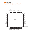
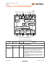
Table 4.1 7-Port Hub Pin Descriptions (continued)
NAME SYMBOL TYPE FUNCTION