


Integrated USB 2.0 Compatible 7-Port Hub
Datasheet
SMSC USB2507 9 Revision 2.3 (08-27-07)
DATASHEET
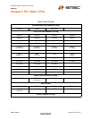
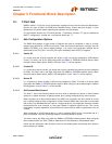
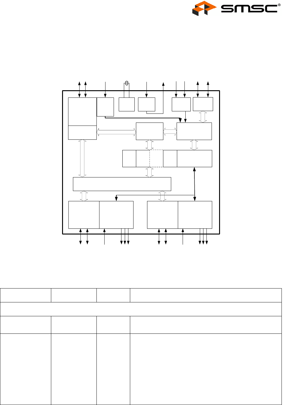
Chapter 4 7-Port Hub Block Diagram
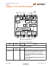
Figure 4.1 7-Port Block Diagram
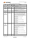
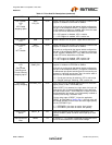
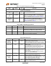
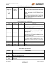
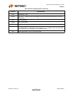
Table 4.1 7-Port Hub Pin Descriptions
NAME SYMBOL TYPE FUNCTION
UPSTREAM USB 2.0 INTERFACE
USB Bus Data USBDN0
USBDP0
IO-U These pins connect to the upstream USB bus data signals.
Detect Upstream
VBUS Power
VBUS_DET I/O12 Detects state of Upstream VBUS power. The SMSC Hub
monitors VBUS_DET to determine when to assert the
internal D+ pull-up resistor (signalling a connect event).
When designing a detachable hub, this pin must be
connected to the VBUS power pin of the USB port that is
upstream of the hub. (Use of a weak pull-down resistor is
recommended.)
For self-powered applications with a permanently attached
host, this pin must be pulled-up to either 3.3V or 5.0V
(typically VDD33).
Upstream
V
BUS
Upstream
PHY
Upstream
USB Data
Repeater
Controller
SIE
Serial
Interface
PLL
24 MHz
Crystal
To
EEPROM
or SMBus
Master
Routing Logic
SCLSD
TT
#1
TT
#2
...
TT
#7
Port
Controller
Downstream
PHY #1
Port #1
OC Sense
Switch Driver
LED Drivers
Downstream
PHY #7
Port #7
OC Sense
Switch Driver
LED Drivers
...
Downstream
USB Data
OC
Sense
Switch/LED
Drivers
Downstream
USB Data
OC
Sense
Switch/LED
Drivers
V
BUS
Power
Detect
Pin
Strapping
Options
Internal
Defaults
Select
3.3V
1.8V
Reg.
1.8V
Cap