


Integrated USB 2.0 Compatible 7-Port Hub
Datasheet
SMSC USB2507 19 Revision 2.3 (08-27-07)
DATASHEET
5.2.1.1 Implementation Characteristics
Please refer to the MicroChip 24AA00 DataSheet for Protocol and Programming specifics.
5.2.1.2 Pull-Up Resistor
The Circuit board designer is required to place external pull-up resistors (10KΩ recommended) on the
SDA/SMBDATA & SCL/SMBCLK/CFG_SELO lines (per SMBus 1.0 Specification, and EEPROM
manufacturer guidelines) to Vcc in order to assure proper operation.
5.2.1.3 I2C EEPROM Slave Address
Slave address is 1010000.
Note: 10-bit addressing is NOT supported.
5.2.2 In-Circuit EEPROM Programming
The EEPROM can be programmed via ATE by pulling RESET_N low (which tri-states the Hub’s
EEPROM interface and allows an external source to program the EEPROM).
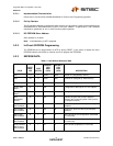
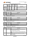
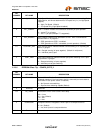
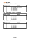
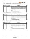
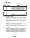
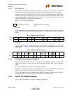
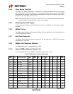
5.2.3 EEPROM DATA
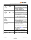
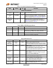
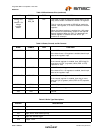
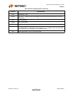
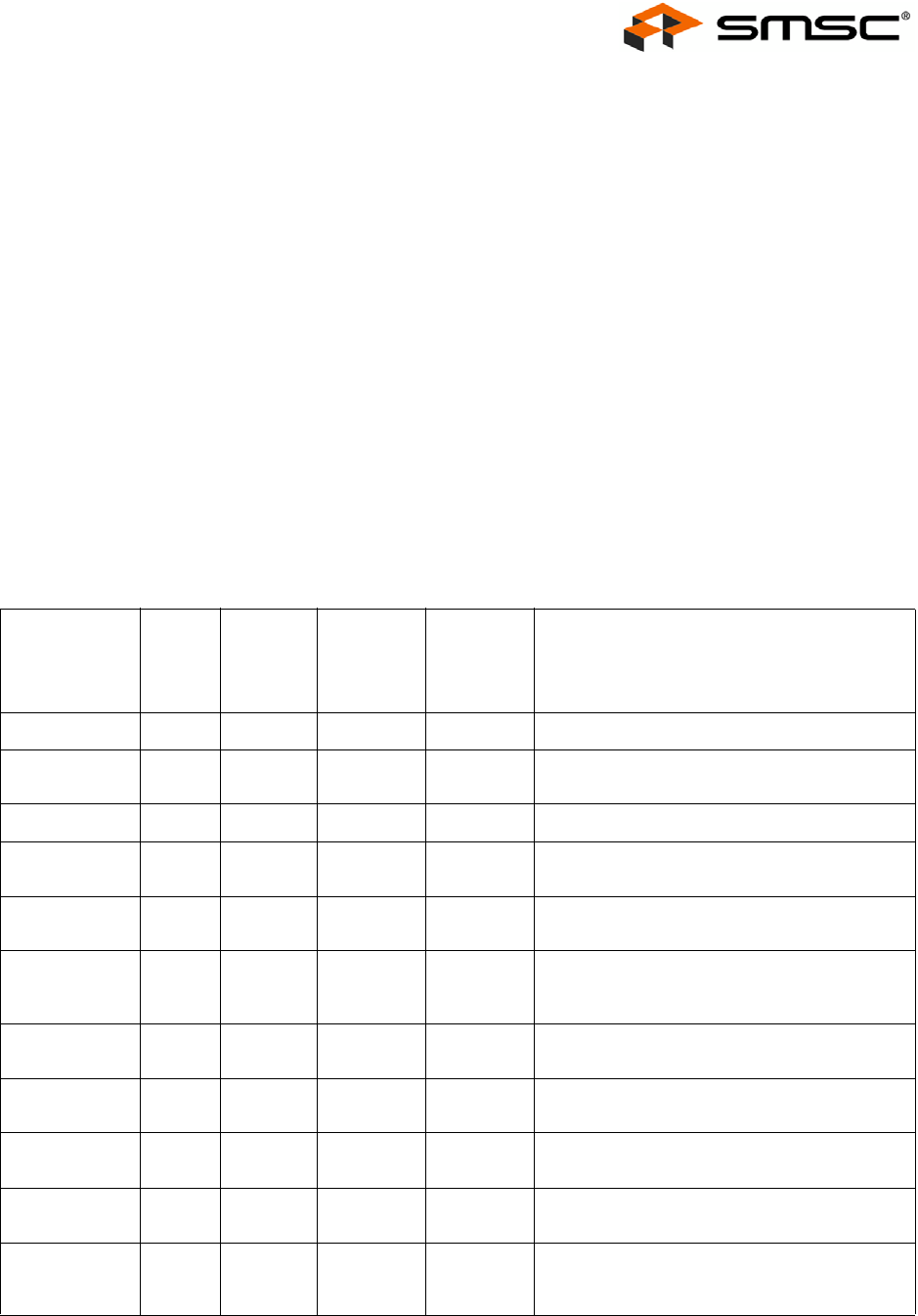
Table 5.1 User-Defined Descriptor Data
FIELD
BYTE
MSB:
LSB
SIZE
(BYTES)
DEFAULT
CFG
SELF
(HEX)
DEFAULT
CFG
BUS
(HEX) DESCRIPTION
VID 1:0 2 0424 0424 Vendor ID (assigned by USB-IF).
PID 3:2 2 2507 2507 Product ID (assigned by Manufacturer).
DID 5:4 2 0000 0000 Device ID (assigned by Manufacturer).
Config Data
Byte 1
6 1 98 1C Configuration data byte #1 for Hub options.
Config Data
Byte 2
7 1 10 90 Configuration data byte #2 for Hub options.
Non
Removable
Device
8 1 00 00 Defines the ports that contain attached
devices (this is used only when Hub is part of
a compound device).
Port Disable
Self-Powered
9 1 00 00 Selects the ports that will be permanently
disabled
Port Disable
Bus-Powered
A 1 00 00 Selects the ports that will be permanently
disabled
Max Power
Self-Powered
B 1 01 01 Max Current for this configuration (expressed
in 2mA units).
Max Power
Bus-Powered
C 1 64 64 Max Current for this configuration (expressed
in 2mA units).
Hub Controller
Max Current
Self-Powered
D 1 01 01 Max Current (expressed in 2mA units).