


Integrated USB 2.0 Compatible 7-Port Hub
Datasheet
SMSC USB2507 27 Revision 2.3 (08-27-07)
DATASHEET
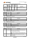
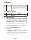
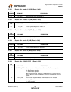
5.3.9.1 Register 00h: Status/Command (Reset = 0x00)
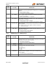
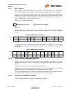
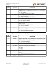
5.3.9.2 Register 01h: Vendor ID (LSB) (Reset = 0x00)
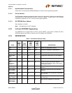
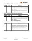
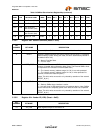
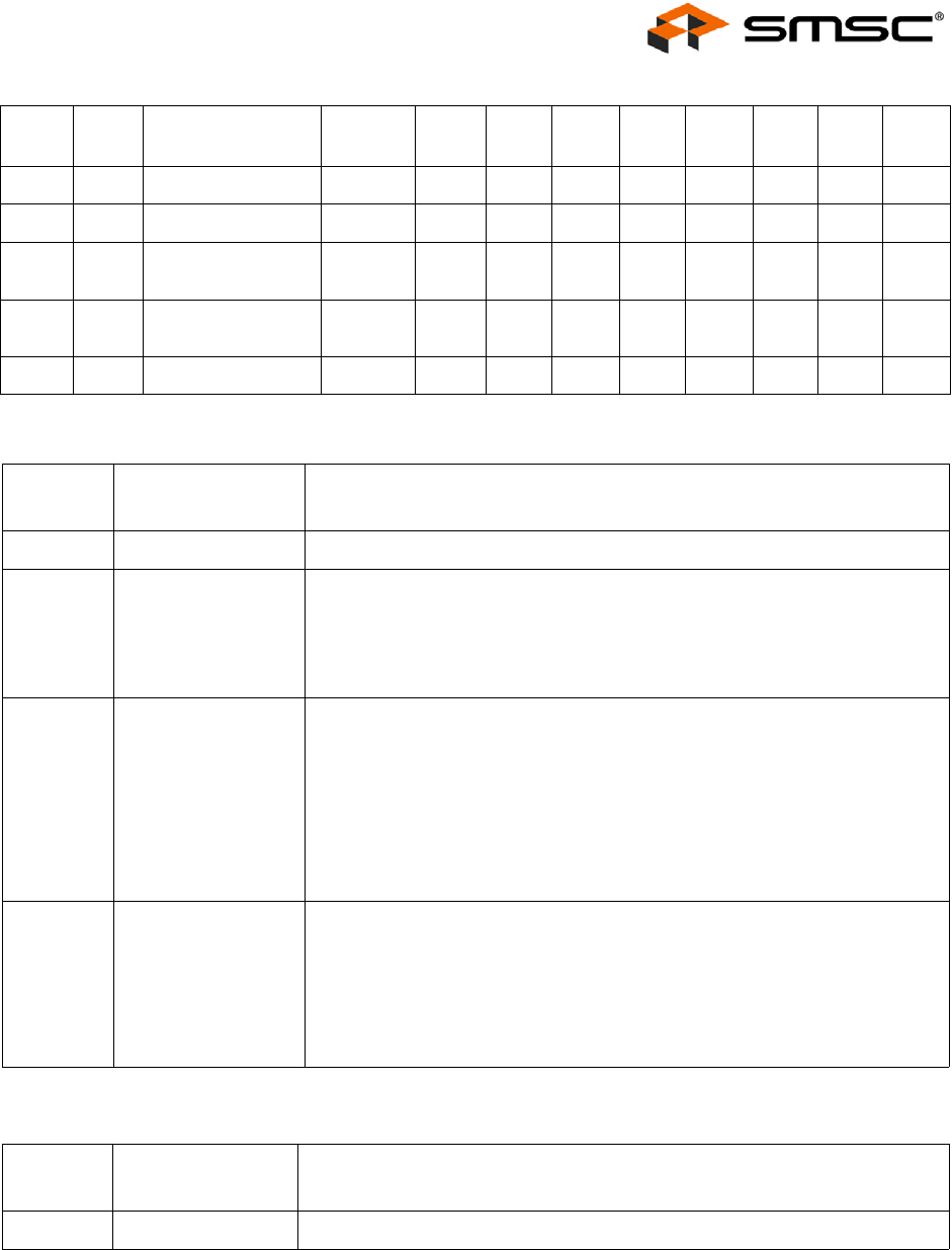
0Ch R/W Max Power (Self) MAXPS 7 6 5 4 3 2 1 0
0Dh R/W Max Power (Bus) MAXPB 7 6 5 4 3 2 1 0
0Eh R/W Hub Controller
Max Current (Self)
HCMCS 7 6 5 4 3 2 1 0
0Fh R/W Hub Controller
Max Current (bus)
HCMCB 7 6 5 4 3 2 1 0
10h R/W Power-on Time PWRT 7 6 5 4 3 2 1 0
BIT
NUMBER BIT NAME DESCRIPTION
7:3 Reserved Reserved. {Note: Software must never write a ‘1’ to these bits}
2 RESET Reset the SMBus Interface and internal memory back to RESET_N assertion
default settings. {Note: During this reset, this bit is automatically cleared to
its default value of 0.}
0 = Normal Run/Idle State.
1 = Force a reset.
1 WRITE_PROT Write Protect: The external SMBus host sets this bit after the Hub’s internal
memory is loaded with configuration data. {Note: The External SMBus Host
is responsible for verification of downloaded data.}
0 = The internal memory (address range 01-10h) is not write protected.
1 = The internal memory (address range 01-10h) is “write-protected” to
prevent unintentional data corruption.}
{Note: This bit is write once and is only cleared by assertion of the external
RESET_N pin.}
0 USB_ATTACH USB Attach & power-down the SMBus Interface.
0 = Default; SMBus slave interface is active.
1 = Hub will signal a USB attach event to an upstream device, Note: SMBus
Slave interface will completely power down after the ACK has completed.
{Note: This bit is write once and is only cleared by assertion of the external
RESET_N pin.}
BIT
NUMBER BIT NAME DESCRIPTION
7:0 VID_LSB Least Significant Byte of the Vendor ID.
Table 5.4 SMBus Slave Interface Register Map (continued)
REG
ADDR R/W REGISTER NAME ABBR
BIT 7
(MSB) BIT 6 BIT 5 BIT 4 BIT 3 BIT 2 BIT 1
BIT 0
(LSB)