


Integrated USB 2.0 Compatible 7-Port Hub
Datasheet
Revision 2.3 (08-27-07) 18 SMSC USB2507
DATASHEET
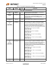
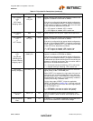
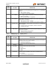
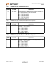
5.1.1.19 Self-powered Hub Controller Current
When in Self-Powered configuration, Maximum current requirements of the Hub Controller in 2mA
increments.
This field is set by the OEM using either the SMBus or EEPROM interface options.
5.1.1.20 Bus-Powered Hub Controller Current
When in Bus-Powered configuration, Maximum current requirements of the Hub Controller in 2mA
increments.
This field is set by the OEM using either the SMBus or EEPROM interface options.
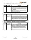
5.1.1.21 Power-On Timer
Time (in 2ms intervals) from the time power-on sequence begins on a port until power is good on that
port. System software uses this value to determine how long to wait before accessing a powered-on
port.
This field is set by the OEM using either the SMBus or EEPROM interface options.
5.1.1.22 Power Switching Polarity
The selection of active state “polarity” for the PRTPWR[7:1] pins is made by a strapping option only.
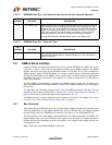
5.1.2 VBus Detect
According to Section 7.2.1 of the USB 2.0 Specification, a downstream port can never provide power
to its D+ or D- pull-up resistors unless the upstream port’s VBUS is in the asserted (powered) state.
The VBUS_DET pin on the Hub monitors the state of the upstream VBUS signal and will not pull-up
the D+ or D- resistor if VBUS is not active. If VBUS goes from an active to an inactive state (Not
Powered), Hub will remove power from the D+ or D- pull-up resistor within 10 seconds.
5.2 EEPROM Interface
The SMSC Hub can be configured via a 2-wire (I2C) EEPROM. (Please see Table 4.1, "7-Port Hub
Pin Descriptions" for specific details on how to enable the I2C EEPROM option).
The Internal state-machine will, (when configured for EEPROM support) read the external EEPROM
for configuration data. The hub will then “attach” to the upstream USB host.
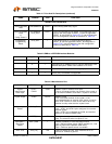
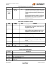
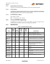
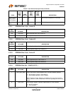
Please see Ta ble 5.1 User-Defined Descriptor Data for a list of data fields available.
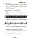
5.2.1 I2C EEPROM
The I2C EEPROM interface implements a subset of the I2C Master Specification (Please refer to the
Philips Semiconductor Standard I2C-Bus Specification for details on I2C bus protocols). The Hub’s I2C
EEPROM interface is designed to attach to a single “dedicated” I2C EEPROM, and it conforms to the
Standard-mode I2C Specification (100kbit/s transfer rate and 7-bit addressing) for protocol and
electrical compatibility.
Note: Extensions to the I2C Specification are not supported.
The Hub acts as the master and generates the serial clock SCL, controls the bus access (determines
which device acts as the transmitter and which device acts as the receiver), and generates the START
and STOP conditions.