


USB 2.0 Hi-Speed Hub Controller
Datasheet
SMSC USB251x 23 Revision 1.0 (3-11-09)
DATASHEET
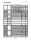
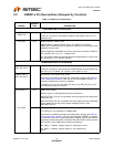
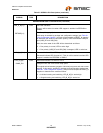
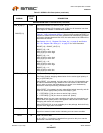
DOWNSTREAM USB 2.0 INTERFACES (continued)
LED_A_N[x:1] /
PRTSWP[x:1]
I/O12 Port LED Indicators
This pin will be active low when LED support is enabled via EEPROM or
SMBus.
Port Swap Strapping Option
If this strap is enabled by package and configuration settings (see Table 8.1,
"Hub Configuration Options"), this pin will be sampled at RESET_N negation
to determine the electrical connection polarity of the downstream USB port
pins (USB_DP and USB_DM).
Also, the active state of the LED will be determined as follows:
‘0’ = Port polarity is normal, LED is active high.
‘1’ = Port polarity (USB_DP and USB_DM) is swapped, LED is active low.
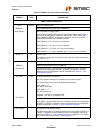
LED_B_N[7:4] I/O12 Enhanced Indicator Port LED for ports 4-7
Enhanced indicator LED for ports 4-7. This pin will be active low when LED
support is enabled via EEPROM or SMBus.
LED_B_N[3] /
GANG_EN
I/O12 Enhanced Indicator Port LED for Port 3
Ganged Power and Over-current strap option
This signal selects between ganged or individual port power and over-current
sensing. If this strap is enabled by package and configuration settings (see
Table 8.1, "Hub Configuration Options"), this pin will be sampled at RESET_N
negation to determine the mode as follows:
‘0’ = Individual sensing and switching, LED_B_N[3] is active high.
‘1’ = Ganged sensing and switching, LED_B_N[3] is active low.
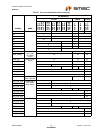
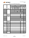
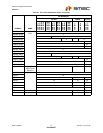
Table 5.2 USB251x Pin Descriptions (continued)
SYMBOL
BUFFER
TYPE DESCRIPTION