


USB 2.0 Hi-Speed Hub Controller
Datasheet
Revision 1.0 (3-11-09) 58 SMSC USB251x
DATASHEET
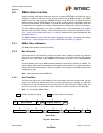
8.6.1.3 RESET_N for SMBus Slave Configuration
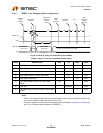
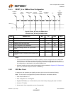
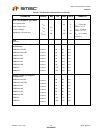
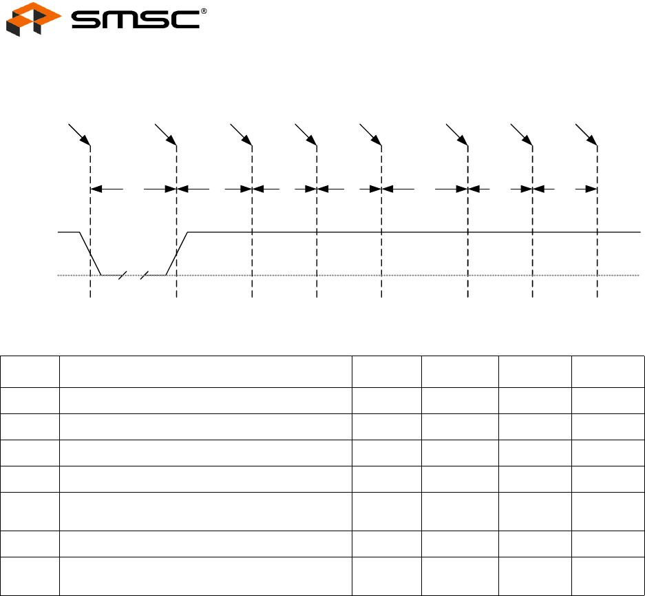
Figure 8.5 Reset_N Timing for SMBus Mode
Notes:
For bus-powered configurations, the 99.5 ms (MAX) is required, and the hub and its associated
circuitry must not consume more than 100 mA from the upstream USB power source during
t2+t3+t4+t5+t6+t7. For Self-Powered configurations, t3 MAX is not applicable and the time to load
the configuration is determined by the external SMBus host.
All power supplies must have reached the operating levels mandated in Chapter 9, DC Parameters,
prior to (or coincident with) the assertion of RESET_N.
8.6.2 USB Bus Reset
In response to the upstream port signaling a reset to the hub, the hub does the following:
Note: The hub does not propagate the upstream USB reset to downstream devices.
1. Sets default address to 0.
2. Sets configuration to: Unconfigured.
3. Negates PRTPWR[x:1] to all downstream ports unless battery charging (BC_EN) is enabled.
4. Clears all TT buffers.
5. Moves device from suspended to active (if suspended).
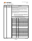
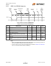
Table 8.9 Reset_N Timing for SMBus Mode
NAME DESCRIPTION MIN TYP MAX UNITS
t1 RESET_N Asserted. 1 μsec
t2 Hub Recovery/Stabilization. 500 μsec
t3 SMBus Code Load (See Note). 250 300 msec
t4 Hub Configuration and USB Attach. 100 msec
t5 Host acknowledges attach and signals USB
Reset.
100 msec
t6 USB Idle. Undefined msec
t7 Completion time for requests (with or without data
stage).
5 msec
t1
t2 t4
t5
t6 t7
RESET_N
VSS
Hardware
reset
asserted
Reset
Negation
SMBus Code
Load
Attach
USB
Upstream
USB Reset
recovery
Idle
Start
completion
request
response
t3
Hub PHY
Stabilization