


USB 2.0 Hi-Speed Hub Controller
Datasheet
SMSC USB251x 25 Revision 1.0 (3-11-09)
DATASHEET
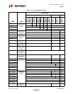
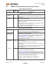
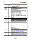
SERIAL PORT INTERFACES
SDA /
SMBDATA /
NON_REM[1]
I/OSD12 Serial Data signal (SDA)
Server Message Block Data signal (SMBDATA)
Non-removable port strap option
If this strap is enabled by package and configuration settings (see Table 8.1),
this pin will be sampled (in conjunction with LOCAL_PWR / SUSP_IND /
NON_REM[0]) at RESET_N negation to determine if ports [7:1] contain
permanently attached (non-removable) devices:
NON_REM[1:0] = ‘00’, All ports are removable.
NON_REM[1:0] = ‘01’, Port 1 is non-removable.
NON_REM[1:0] = ‘10’, Ports 1 & 2 are non-removable.
NON_REM[1:0] = ‘11’, When available, ports 1 2 & 3 are non-removable.
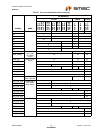
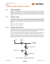
RESET_N IS RESET Input
The system can reset the chip by driving this input low. The minimum active
low pulse is 1 μs.
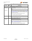
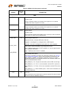
SCL /
SMBCLK /
CFG_SEL[0]
I/OSD12 Serial Clock (SCL)
System Management Bus Clock (SMBCLK)
Configuration Select: The logic state of this multifunction pin is internally
latched on the rising edge of RESET_N (RESET_N negation), and will
determine the hub configuration method as described in Table 8.1, "Hub
Configuration Options".
HS_IND /
CFG_SEL[1]
I/O12 Hi-Speed Upstream Port Indicator
HS_IND: Hi-speed Indicator for upstream port connection speed.
The active state of the LED will be determined as follows:
CFG_SEL[1] = ‘0’,
HS_IND is active high,
CFG_SEL[1] = ‘1’,
HS_IND is active low,
‘Asserted’ = the hub is connected at HS
‘Negated’ = the hub is connected at FS
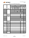
Configuration Programming Select
CFG_SEL[1]: The logic state of this pin is internally latched on the rising edge
of RESET_N (RESET_N negation), and will determine the hub configuration
method as described in Table 8.1, "Hub Configuration Options".
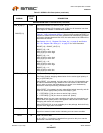
CFG_SEL[2] I Configuration Programming Select
The logic state of this pin is internally latched on the rising edge of RESET_N
(RESET_N negation), and will determine the hub configuration method as
described in Table 8.1, "Hub Configuration Options". When the CFG_SEL[2]
pin is unavailable, then the logic is internally tied to ‘0’.
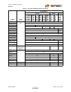
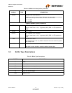
Table 5.2 USB251x Pin Descriptions (continued)
SYMBOL
BUFFER
TYPE DESCRIPTION