USB 2.0 Hi-Speed Hub Controller
Datasheet
Revision 1.0 (3-11-09) 24 SMSC USB251x
DATASHEET
DOWNSTREAM USB 2.0 INTERFACES (continued)
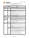
LED_B_N[2:1] /
BOOST[1:0]
I/O12 Enhanced Indicator Port LED for ports 1 and 2
Enhanced indicator LED for ports 1 and 2. This pin will be active low when
LED support is enabled via EEPROM or SMBus.
If this strap option is enabled by package and configuration settings (see
Table 8.1, "Hub Configuration Options"), this pin will be sampled at RESET_N
negation to determine if all PHY ports (upstream and downstream) operate at
a normal or boosted electrical level. Also, the active state of the LEDs will be
determined as follows:
See Section 8.2.1.27, "Register F6h: Boost_Up," on page 45 and Section
8.2.1.29, "Register F8h: Boost_4:0," on page 47 for more information.
BOOST[1:0] = BOOST_IOUT[1:0]
BOOST[1:0] = ‘00’,
LED_B_N[2] is active high,
LED_B_N[1] is active high.
BOOST[1:0] = ‘01’,
LED_B_N[2] is active high,
LED_B_N[1] is active low.
BOOST[1:0] = ‘10’,
LED_B_N[2] is active low,
LED_B_N[1] is active high.
BOOST[1:0] = ‘11’,
LED_B_N[2] is active low,
LED_B_N[1] is active low.
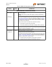
PRTPWR_POL IPU Port Power Polarity Strapping
Port Power Polarity strapping determination for the active signal polarity of
the [x:1]PRTPWR pins.
While RESET_N is asserted, the logic state of this pin will (through the use
of internal combinatorial logic) determine the active state of the PRTPWR
pins in order to ensure that downstream port power is not inadvertently
enabled to inactive ports during a hardware reset.
When RESET_N is negated, the logic value will be latched internally, and will
retain the active signal polarity for the PRTPWR[x:1] pins.
‘1’ = PRTPWR[x:1]_P/N pins have an active ‘high’ polarity
‘0’ = PRTPWR[x:1]_P/N pins have an active ‘low’ polarity
Warning: Active low port power controllers may glitch the downstream port
power when the system power is first applied. Care should be taken when
designing with active low components.
When PRTPWR_POL is not an available pin on the package, the hub will only
support active high power controllers.
OCS_N[x:1] IPU Over-Current Sense
Input from external current monitor indicating an over-current condition.
RBIAS I-R USB Transceiver Bias
A 12.0 k
Ω (+/- 1%) resistor is attached from ground to this pin to set the
transceiver’s internal bias settings.
Table 5.2 USB251x Pin Descriptions (continued)
SYMBOL
BUFFER
TYPE DESCRIPTION


