USB MultiSwitch
TM
Hub
Datasheet
Revision 1.91 (08-22-07) 14 SMSC USB2524
DATASHEET
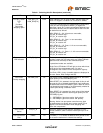
Assign
Downstream
Ports to Upstream
Host Ports
PRT_ASSIGN
[3:0]
I Port Assign Interface: Operates in either Embedded mode,
or Peripheral mode. See Chapter 6, Assigning Ports for
additional details.
SERIAL PORT INTERFACE
Serial Data/SMB
Data
SDA/SMBDATA IOSD12 (Serial Data)/(SMB Data) signal.
Serial Clock/SMB
Clock
&
Configuration
Programming
Select
SCL/SMBCLK/
CFG_SEL0
IOSD12 (Serial Clock)/(SMB Clock) signal.
CFG_SEL0: The logic state of this multifunction pin is
internally latched on the rising edge of RESET_N
(RESET_N negation), and will determine the hub
configuration method as described in Table 4.2.
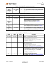
Configuration
Programming
Select
CFG_SEL1 I The logic state of this pin is internally latched on the rising
edge of RESET_N (RESET_N negation), and will determine
the hub configuration method as described in Table 4.2.
Configuration
Programming
Select
CFG_SEL2 I The logic state of this pin is internally latched on the rising
edge of RESET_N (RESET_N negation), and will determine
the hub configuration method as described in Table 4.2.
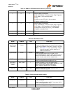
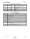
Table 4.2 SMBus or EEPROM Interface Behavior
NAME NAME NAME FUNCTION
CFG_SEL2 CFG_SEL1 CFG_SEL0 SMBus or EEPROM interface behavior.
0 0 0 Internal Default Configuration
PRT_ASSIGN[3:0] = Embedded Mode.
Strap options on pins LED_A[4:1]_N are enabled.
LED Mode = USB Mode
0 0 1 Configured as an SMBus slave for external download of
user-defined descriptors.
SMBus slave address is :0101100
Strap options on pins LED_A[4:1]_N are disabled
LED Mode = See Chapter 8, LED Interface Description
0 1 0 Internal Default Configuration
PRT_ASSIGN[3:0] = Peripheral Mode (Level Triggered)
Strap options on pins LED_A[4:1]_N are enabled.
No support for unassigned Ports.
LED Mode = USB Mode
0 1 1 2-wire (I2C) EEPROMS are supported,
LED Mode = See Chapter 8, LED Interface Description
Table 4.1 Switching Hub Pin Descriptions (continued)
NAME SYMBOL TYPE FUNCTION


