


USB MultiSwitch
TM
Hub
Datasheet
SMSC USB2524 25 Revision 1.91 (08-22-07)
DATASHEET
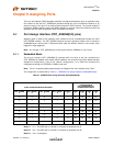
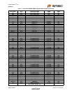
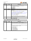
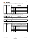
7.1.4.10 Register 09h: Non-Removable Device (Reset = 0x00)
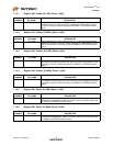
5 PRT_ASSIGN_CFG Port Assignment Configuration:
‘0’ = Port assignment is controlled by hardware interface pins
‘1’ = Port assignment is controlled by:
PORT_ASSIGN_12
PORT_ASSIGN_34
PORT_ASSIGN_56
PORT_ASSIGN_7
4:3 Reserved Reserved, always = ‘0’.
2:1 LED_MODE LED Mode Selection: The LED_A[4:1]_N and LED_B[4:1]_N pins support
several different modes of operation (depending upon OEM implementation of
the LED circuit).
‘00’ = USB Mode, (see USB Mode: on page 44 for description)
‘01’ = Host Ownership and Port Speed LED indicator, (see Host Ownership and
Port Speed LED Indication: on page 45 for description)
‘10’ = Basic Host Ownership LED indicator, (see Basic Host Owner LED
Indication: on page 44 for description)
‘11’ = Same as "00", USB Mode
Warning: Do not enable an LED mode that requires LED pins that are not
available in the specific package being used in the implementation!
0 STRING_EN Enables String Descriptor Support
‘0’ = String Support Disabled
‘1’ = String Support Enabled
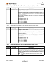
BIT
NUMBER BIT NAME DESCRIPTION
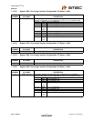
7:0 NR_DEVICE Non-Removable Device: Indicates which port(s) include non- removable
devices. ‘0’ = port is removable, ‘1’ = port is non- removable.
Informs the Host if one of the active ports has a permanent device that is un-
detachable from the Hub. (Note: The device must provide its own descriptor
data.)
When using the internal default option, the NON_REM[1:0] pins will designate
the appropriate ports as being non- removable.
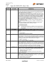
Bit 7= Reserved, always = ‘0’.
Bit 6= Reserved, always = ‘0’.
Bit 5= Reserved, always = ‘0’.
Bit 4= 1; Port 4 is disabled.
Bit 3= 1; Port 3 non-removable.
Bit 2= 1; Port 2 non-removable.
Bit 1= 1; Port 1 non-removable.
Bit 0 is Reserved, always = ‘0’.
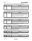
BIT
NUMBER BIT NAME DESCRIPTION