USB MultiSwitch
TM
Hub
Datasheet
Revision 1.91 (08-22-07) 24 SMSC USB2524
DATASHEET
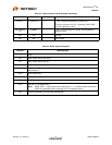
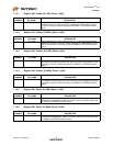
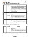
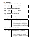
7.1.4.8 Register 07h: Configuration Data Byte 2 (Reset = 0x00)
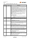
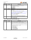
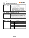
7.1.4.9 Register 08h: Configuration Data Byte 3 (Reset = 0x00)
BIT
NUMBER BIT NAME DESCRIPTION
7 DYNAMIC Dynamic Power Enable: Controls the ability of the Hub to automatically
change from Self-Powered operation to Bus- Powered operation if the local
power source is removed or is unavailable (and from Bus-Powered to Self-
Powered if the local power source is restored). {Note: If the local power source
is available, the Hub will always switch to Self-Powered operation.}
When Dynamic Power switching is enabled, the Hub detects the availability of
a local power source by monitoring the external SELF_PWR pin. If the Hub
detects a change in power source availability, the Hub immediately
disconnects and removes power from all downstream devices and disconnects
the upstream port. The Hub will then re-attach to the upstream port as either
a Bus-Powered Hub (if local-power in unavailable) or a Self-Powered Hub (if
local power is available).
0 = No Dynamic auto-switching.
1 = Dynamic Auto-switching capable.
6 Reserved Reserved, always = ‘0’.
5:4 OC_TIMER OverCurrent Timer: Over Current Timer delay.
00 = 0.1ms
01 = 2ms
10 = 4ms
11 = 6ms
3 COMPOUND Compound Device: Allows the OEM to indicate that the Hub is part of a
compound (see the USB Specification for definition) device. The applicable
port(s) must also be defined as having a “Non-Removable Device”.
Note: When configured via strapping options, declaring a port as non-
removable automatically causes the hub controller to report that it is part of a
compound device.
0 = No.
1 = Yes, Hub is part of a compound device.
2:1 Reserved Reserved, always = ‘0’.
0 BOOST_IOUT Upstream USB electrical signaling drive strength Boost Bit.
Note: This is used for long-trace length designs where additional electrical
signal boost may be required to support standard USB signal levels
at the far end of a cable.
‘0’ = Normal electrical drive strength.
‘1’ = Elevated electrical drive strength.
BIT
NUMBER BIT NAME DESCRIPTION
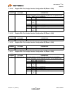
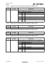
7:6 PRT_ASSIGN_MODE Port Assignment Interface Mode:
‘00’ = Port Assign Interface is configured for Programmable Mode (8
configurations) (3-wire)
‘01’ = Port Assign Interface is configured for Direct Port Control. (4-Wire), Level
Sensitive.
‘10’ = Port Assign Interface is configured for Direct Port Control. (4-Wire), edge
Sensitive, and Unassigned state is not supported.
‘11’ = Port Assign Interface is configured for Direct Port Control. (4-Wire), edge
Sensitive, and the Unassigned state is supported.


