


USB MultiSwitch
TM
Hub
Datasheet
SMSC USB2524 45 Revision 1.91 (08-22-07)
DATASHEET
8.3 Host Ownership and Port Speed LED Indication:
All 8 LED pins are used in this mode in conjunction with 8 Dual-color LEDs (each LED pair in a single
package) to indicate which upstream Host owns each specific downstream Port, as well as the speed
that the downstream device is operating at.
Each dual-color LED provides two separate colors (commonly Green and Red). If each of these
separate colors are pulsed on and off at a rapid rate, a user will see a third color (in this example,
Orange). By this means, 4 different “color” states are possible (Green, Red, Orange, and Off).
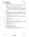
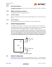
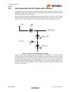
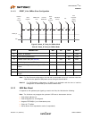
Figure 8.1 Dual Color LED Implementation Example
Figure 8.1 shows a simple example of how this LED circuit will be implemented. The Circuit will need
to be replicated for each of the 8 LED pins on the USB2524. In this circuit, when the LED pin is driven
to a logic low state, the Green LED will Light up. When the LED pin is driven to a Logic High state
the Red LED will Light up. When a 1KHz square wave is driven out on the LED pin, the Green and
Red LED’s will both alternately light up giving the effect of the color Orange. When nothing is driven
out on the LED pin (i.e. the pin floats to a “tri-state” condition), neither the Green or Red LED will light
up, this is the “Off” state.
LED pin
Green LED
Red LED
3.3V
General
Purpose
Diode
Current limiting
resistor
Connect to other
dual color diodes.