High Speed Inter-Chip USB 2.0 Hub and Flash Media Controller
Datasheet
SMSC USB4640/USB4640i 51 Revision 1.0 (06-01-09)
DATASHEET
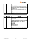
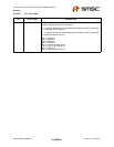
8.4.5.5 11Ch-122h: Combo LUN 4 Identifier String
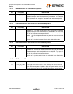
8.4.5.6 123h-145h: Not Applicable
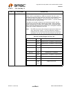
8.4.5.7 146h: Dynamic Number of Extended LUNs
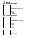
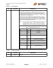
8.4.5.8 147h-14Bh: Device to LUN Mapping
8.4.5.9 14Ch-17Bh: Not Applicable
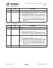
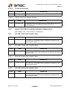
8.4.5.10 17Ch -17Fh: Non-Volatile Storage Signature for Extended Configuration
BYTE NAME DESCRIPTION
6:0 CLUN4_ID_STR If the device to LUN mapping bytes have configured this LUN to be a combo
LUN, then these strings will be used to identify the LUN rather than the
device identifier strings.
BYTE NAME DESCRIPTION
34:0 Not Applicable Not applicable.
BIT NAME DESCRIPTION
7:0 DYN_NUM_
EXT_LUN
These bytes are used to specify the number of LUNs the device exposes to
the host. These bytes are also used for icon sharing by assigning more than
one LUN to a single icon. This is used in applications where the device
utilizes a combo socket and the OEM wishes to have only a single icon
displayed for one or more interfaces.
If this field is set to "FF", the program assumes that you are using the default
value and icons will be configured per the default configuration.
BYTE NAME DESCRIPTION
4:0 DEV_LUN_MAP These registers map a device controller (SD/MMC, SM (Note 8.2), and MS)
to a Logical Unit Number (LUN). The device reports the mapped LUNs to
the USB host in the USB descriptor during enumeration. The icon installer
associates custom icons with the LUNs specified in these fields.
Setting a register to "FF" indicates that the device is not mapped. Setting all
of the DEV_LUN_MAP registers for all devices to "FF" forces the use of the
default mapping configuration. Not all configurations are valid. Valid
configurations depend on the hardware, packaging, and OEM board layout.
The number of unique LUNs mapped must match the value in the Section
8.4.3.7, "D3h: Dynamic Number of LUNs," on page 40.
BIT NAME DESCRIPTION
49:0 Not Applicable Not applicable.
BYTE NAME DESCRIPTION
3:0 NVSTORE_SIG2 This signature is used to verify the validity of the data in the upper 256 bytes
if a 512 byte (4 kilobytes) EEPROM is used, otherwise this bank is a read-only
configuration area. The signature must be set to 'ecf1'.


