


High Speed Inter-Chip USB 2.0 Hub and Flash Media Controller
Datasheet
Revision 1.0 (06-01-09) 54 SMSC USB4640/USB4640i
DATASHEET
Chapter 9 AC Specifications
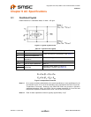
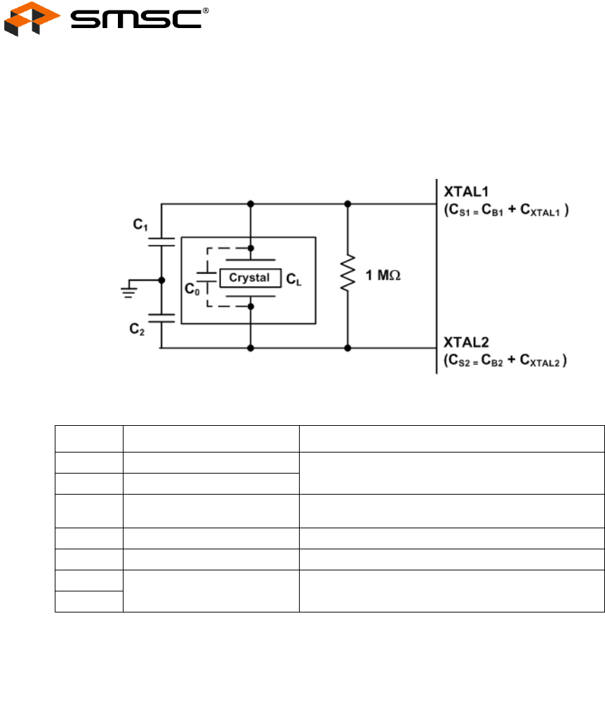
9.1 Oscillator/Crystal
Parallel Resonant, Fundamental Mode, 24 MHz ± 350 ppm.
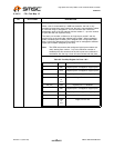
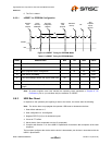
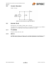
Figure 9.1 Typical Crystal Circuit
Table 9.1 Crystal Circuit Legend
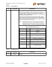
Figure 9.2 Capacitance Formulas
Note 9.1 C
0
is usually included (subtracted by the crystal manufacturer) in the specification for C
L
and should be set to ‘0’ for use in the calculation of the capacitance formulas in Figure 9.2,
"Capacitance Formulas". However, the OEM PCB itself may present a parasitic
capacitance between XTAL1 and XTAL2. For an accurate calculation of C
1
and C
2,
take
the parasitic capacitance between traces XTAL1 and XTAL2 into account.
Note 9.2 Each of these capacitance values is typically approximately 18 pF.
SYMBOL DESCRIPTION IN ACCORDANCE WITH
C
0
Crystal shunt capacitance
Crystal manufacturer’s specification (See Note 9.1)
C
L
Crystal load capacitance
C
B
Total board or trace
capacitance
OEM board design
C
S
Stray capacitance SMSC IC and OEM board design
C
XTAL
XTAL pin input capacitance SMSC IC
C
1
Load capacitors installed on
OEM board
Calculated values based on Figure 9.2,
"Capacitance Formulas" (See Note 9.2)
C
2
C
1
= 2 x (C
L
–
C
0
) – C
S1
C
2
= 2 x (C
L
–
C
0
) – C
S2