


– 29 –
6. Interface
This appendix provides detailed specifications for the printer’s standard serial
interface.
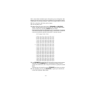
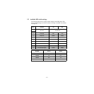
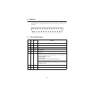
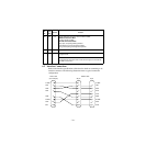
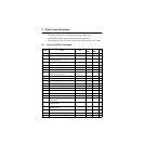
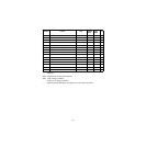
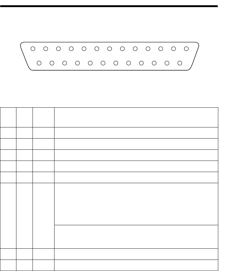
6.1 Pins and Signal Names
Pin
No.
Signal
Name
Direction Function
1FG — Frame ground
2 TXD OUT Transmission data
3 RXD IN Receive data
4 RTS OUT Same as DTR signal
5 N.C. Not connected
6 DSR IN • DIP Switch 9 = OFF
In DTR/DSR communication mode when Memory Switch4-5 = 0, indicates whether data
receive from host is enabled or disabled.
Space: Receive enabled
Mark: Receive disabled
This signal is not checked in the X-ON/X-OFF communication mode.
• DIP Switch 9 = ON
This signal used for external reset. Printer is reset whenever signal is in mark state with
pulse width of 1mS or more.
7 SG Signal ground
8 -19 N.C. Not connected
13
25
1
14