


– 108 –
APPENDIX
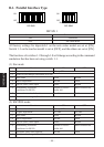
Notes:1. Pin 1 must be shield drain wire connected to peripheral device
frame ground.
2. It is not possible to drive two drives simultaneously.
3. The peripheral drive duty must satisfy the following:
ON time / (ON time + OFF time) ≤ 0.2
4. The resistance of the peripheral drive solenoid must be 24 Ω or
higher.
If it is lower than 24 Ω, over-current may flow into the solenoid,
causing the solenoid to burn.
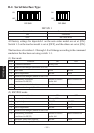
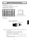
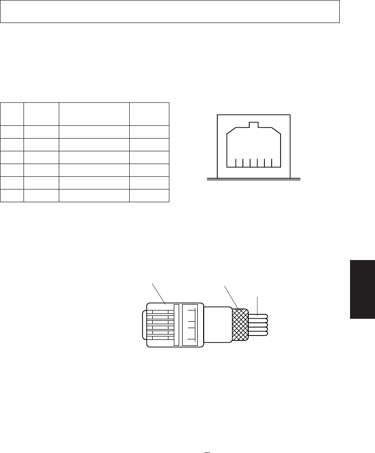
Modular plug
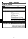
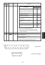
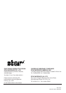
Peripheral Drive Connector
Pin No.
Signal
Function
I/O
name direction
1 FG Frame ground —
2 DRD1 Drive signal 1 OUT
3 +24V Drive power OUT
4 +24V Drive power OUT
5 DRD2 Drive signal 2 OUT
6 DRSNS Sense signal IN
61
<Viewed from Connector Surface>
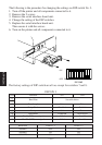
Appendix E: Periheral Unit Drive Circuit
Peripheral unit drive circuit connector only connects to peripheral units such as
cash drawers, etc.
Do not connect it to a telephone.
Use cables which meet the following specifications.
16
Modular plug: MOLEX 90075-0007,
AMP641337, or BURNDY B-66-4
Wire lead
Shield