


CH APT ER 3
PARTS LIST
HOW TO USE PARTS LIST
(1) DRWG. NO.
is column shows the drawing number of the illustration.
(2) REVISED EDITION MARK
is column shows a revision number.
Part that have been added in the revised edition are indicated with “#”.
Part that have been abolished in the revised edition are indicated with “*”.
#1 : First edition Second edition *1 : First edition Second editon
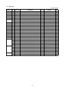
(3) PART NO.
Parts numbers must be notied when ordering replacement parts. Parts described as “NPN” have no parts
number and are not in stock, i.e., unavailable.
(4) PARTS NAME
Parts names must be notied when ordering replacement parts.
(5) Q’TY
is column shows the number of the part used as indicated in the gure.
(6) REMARKS
When dierences in specications exist depending on location/destination.
(7) RANK
Parts marked “S” in the rank column can be ordered. Other parts, as a rule, cannot be supplied even if ordered.
Parts marked “O” are optional parts.
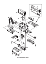
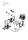
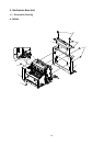
1. Printer Assembly ..........................13 8. Operation Panel Board .................47
1-1. Disassembly Drawing ..............13 8-1. Circuit Diagram ........................47
1-2. Parts List ...................................15 8-2. Component Layout ..................
47
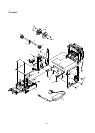
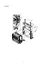
2. Mechanism Base Unit ..................16
8-3. Parts List ...................................
47
2-1. Disassembly Drawing ..............16
9. Snout Board ..................................48
2-2. Parts List ...................................18 9-1.
Circuit Diagram ........................48
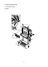
3. Printer Mechanism Unit ...............19
9-2. Component Layout ..................
48
9-3. Parts List ...................................
48
3-1. Disassembly Drawing ..............19
3-2. Parts List ...................................21
10. Serial Interface Board(25pin) .......49
4. Sub-Assembly ...............................23
10-1. Circuit Diagram ........................49
10-2. Parts List ...................................50
4-1. Frame R Unit .............................23
4-2. Frame L Unit .............................24
11. Serial Interface Board(9pin) .........51
4-3. Board chassis L Unit ...............25
11-1. Circuit Diagram ........................51
4-4. Presenter Unit PR521 ...............26
11-2. Parts List ...................................
52
4-5. Paper Guide Unit (PR521) ........28
12. Parallel Interface Board ...............53
4-6. Guide Frame Unit .....................
29
12-1. Circuit Diagram ........................53
4-7. Head Unit ..................................30
12-2. Parts List ...................................
54
4-8. Platen Holder Unit ....................
31
4-9. Paper Guide Unit ......................32
13. USB Interface Board .....................55
5. Block Diagram ..............................33
13-1. Circuit Diagram ........................55
13-2. Component Layout ..................56
6. Main Logic Board .........................34
13-3. Parts List ...................................57
6-1. Circuit Diagram ........................34
14. Ethernet Interface Board ..............58
6-2. Component Layout
6-3. Circuit Number Dia
..................
gram ..........
39
40
14-1. Circuit Diagram ........................58
14-2. Component Layout ..................63
6-4. Parts List ...................................41
14-3. Parts List ...................................
64
7. Sub Board .....................................46
7-1. Circuit Diagram ........................46
7-2. Component Layout ..................
46
7-3. Parts List ...................................
46