


- 4 -
1.2 Adjustment of the NE Sensor (TUP592 Only)
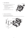
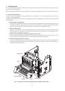
1. Turn the printer o and unplug the power cord.
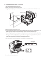
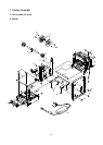
2. Remove the screws. en, remove the board chassis.
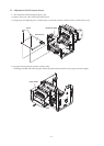
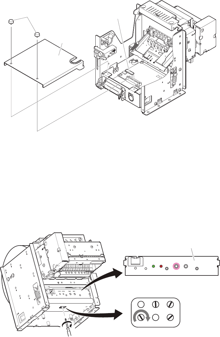
3. Using the tip of a ballpoint pen or a similar object, set the DIP switches as follows: DSW1-4 OFF, DSW1-5 ON.
Screw
Board chassis
DIP Switch DSW1
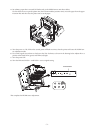
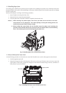
4. Set unused roll paper that will actually be use.
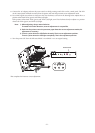
5. Connect the AC adapter and turn the power switch on while pressing switch SW2 on the control panel. e LED
on the control panel will ash two times, then the printer will enter the NE sensor adjustment mode.
6. Use a small regular screwdriver to slowly turn the VR6 clockwise, as shown in the drawing below. Adjust this to
a position where both LED1 (green) and LED2 (red) light. If it is not possible to adjust to a position where both
LED1 (green) and LED2 (red) light, adjust to a position where LED1 (green) is extinguished and LED2 (red) is lit.
Note: When tilting the unit, be careful that the paper does not fall out.
7. Turn the power OFF. Turn the DIP switch DSW 1-4 and DSW 1-5 to its original setting.
is completes the NE sensor adjustment.
LED1
LED2
SW2 SW1
Control Panel